Image forming apparatus

Active Publication Date: 2006-08-10
KONICA MINOLTA BUSINESS TECH INC
View PDF2 Cites 0 Cited by
  • Summary
  • Abstract
  • Description
  • Claims
  • Application Information

AI Technical Summary

Benefits of technology

[0021] a control unit to control the alternating-current power supply,
[0022] wherein the control unit controls a

Problems solved by technology

The technique disclosed in patent document 4 cannot be used as a measure in a case where deterioration of a toner has progressed due to increase in the developing agent holding time when developing an image with a low printing rate.
Consequently, problems concerning the progress of the deterioration of the toner, toner scattering, the deterioration of image quality, and the like are caused.
Moreover, when a developing agent stays in the developing apparatus and gets deteriorated, there is also a case in which the deterioration of the toner at the larger particle diameter side or at the smaller particle diameter side is large.
Accordingly, it became clear that the conventional techniques including the prior art mentioned above cannot prevent the selective development nor prevent the changes in image quality by the selective development sufficiently.
For example, by the technique disclosed in patent document 3, since the technique does not prevent any selective development while an image processing is conducted, image formation is performed by development accompanied with the selective development until ejection of toner is executed, and the deterioration of image quality cannot be fully prevented.
However, it is very difficult to adjust the setting or the apparatus configuration so as not to cause any selective development, and the changes in developing agents due to the selective development after a long period of operation and the changes of image quality is result are inevitable.
Thus, the deterioration of the image quality due to the selective development cannot be fully prevented by an adjustment of the setting or the apparatus configuration.

Method used


Image

  • Image forming apparatus
  • Image forming apparatus
  • Image forming apparatus

Examples


first embodiment

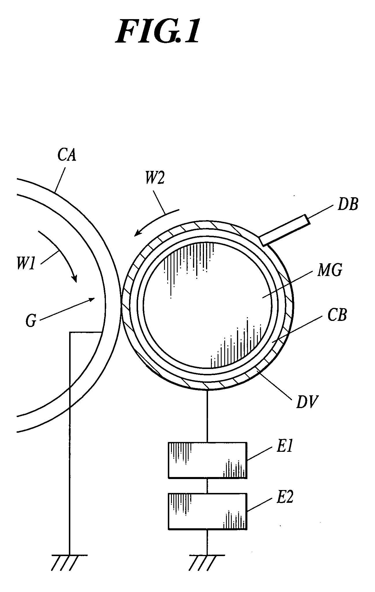
[0039] First of all, with reference to FIGS. 1-4, selective development and the correction of the selective development in first embodiment of the present invention are described.

[0040] In FIG. 1, with regard to an image carrying body CA, which rotates clockwise as shown by an arrow W1, a developing agent carrying body CB, which is arranged to be opposed to the image carrying body CA rotates counterclockwise as shown by an arrow W2, and development is performed by a developing agent layer DV formed on the developing agent carrying body CB.

[0041] As the developing agent of the developing agent layer DV, a two-component developing agent including a toner and a magnetic carrier, and a one-component developing agent including a toner as the principal component thereof without including any carriers are used. For forming an image having high resolution and an excellent tone reproduction, a two-component developing agent using a small diameter toner is preferable, and, in the formation ...

second embodiment

[0111] Hereinafter, a second embodiment of the present invention is described. However, these descriptions do not limit the technical ranges of claims and the meanings of terms.

[Image Forming Apparatus]

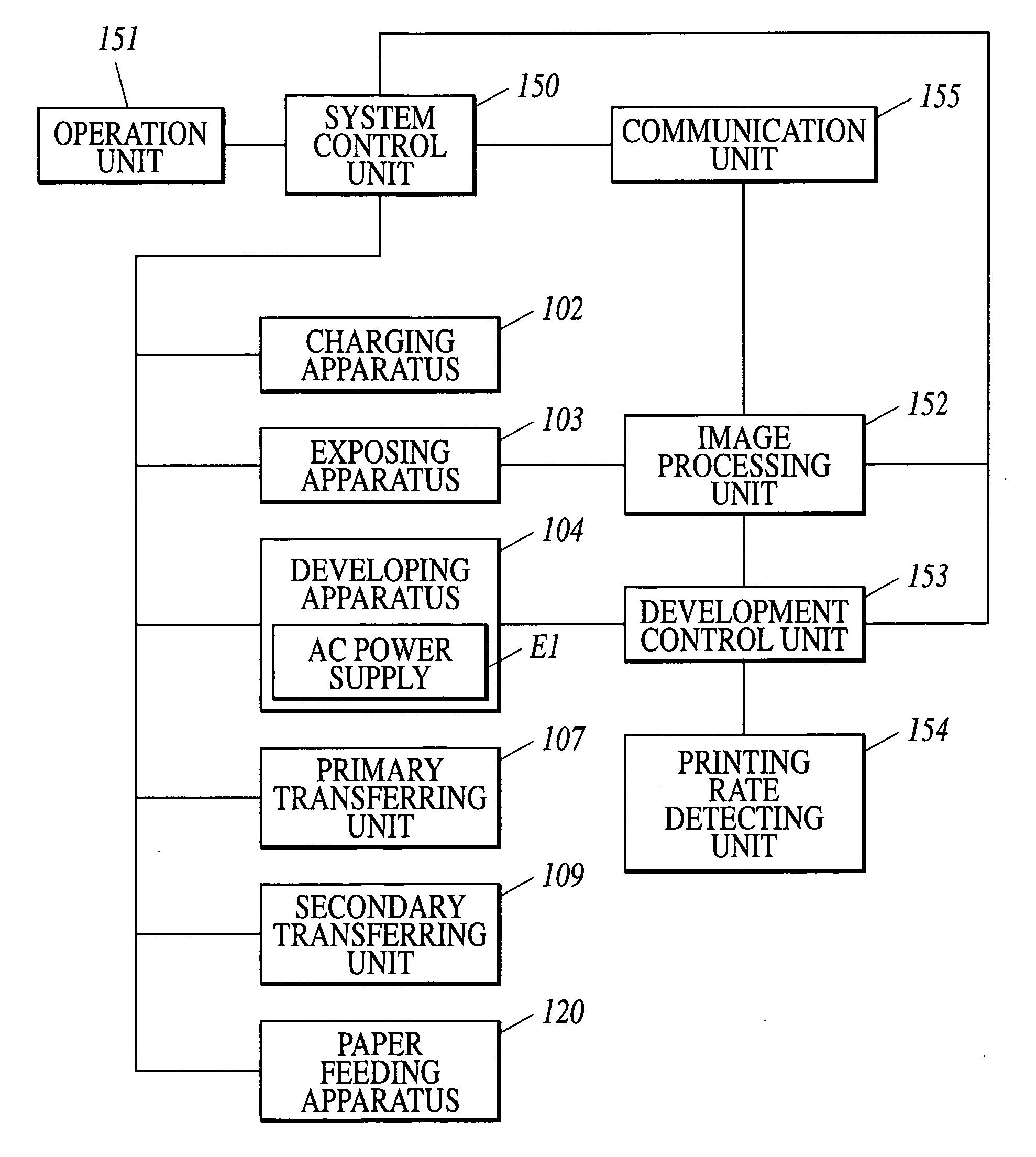
[0112]FIG. 7 is a configuration diagram of an image forming apparatus according to second embodiment.

[0113] The image forming apparatus 2A is called as a tandem type color image forming apparatus, and composed of a plurality of sets of image forming unit 110Y, 110M, 110C, 110K, a belt-like intermediate transfer body 106, a paper feeding-apparatus 120, and a fixing apparatus 130.

[0114] The image forming unit 110Y which forms an image of a yellow (Y) color includes charging apparatus 102Y arranged around a photosensitive drum 101Y as an image carrying body, exposing apparatus 103Y, a developing apparatus 104Y as a developing unit, and cleaning unit 105Y. The image forming unit 110M which forms an image of a magenta (M) color includes a photosensitive drum 101M as an image carrying b...

example 1

[0173] direct-current voltage Vdc: −500V

[0174] alternating voltage Vac:

[0175] 1.0 kV(pp) when printing rate equal to or more than 2%

[0176] 1.5 kV(pp) when printing rate less than 2%

[0177] alternating current frequency: 5 kHz (pp)

[0178] development interval Ds: 0.3 mm

[0179] (shortest distance between image carrying body and developing agent carrying body)

[0180] speed ratio Vs / Vp: 2

[0181] (ratio of line speed ratio Vs of developing agent carrying body and linear speed Vp of image carrying body; image carrying body and developing agent carrying body move in same direction)

[0182] developing agent conveying quantity M: 200-240 g / m2

[0183] In comparison example 1, the image was formed under the same conditions as those of Example 1 except that the alternating voltage Vac(pp) was set to be constant at 1.0 kV, independent of the printing rate.

[0184] The results of the image quality evaluation at the stage at which 5000 images with the printing rate of 1% have been formed, are as s...


PUM


Abstract

An image forming apparatus includes: an image carrying body; a latent image forming unit to form an electrostatic latent image on the image carrying body; a developing unit to develop the electrostatic latent image on the image carrying body to form a toner image, the developing unit including a developing agent carrying body to carry a developing agent in a development region, and a direct-current power supply and an alternating-current power supply, both applying a developing bias voltage to the developing agent carrying body, the developing bias voltage generated by superimposing a direct-current voltage to an alternating voltage; a printing rate detecting unit to detect a printing rate; and a control unit to control the alternating-current power supply, wherein the control unit controls an output of the alternating-current power supply based on a detection result of the printing rate detecting unit.

Description

BACKGROUND OF THE INVENTION [0001] 1. Field of the Invention [0002] The present invention relates to an image forming apparatus of an electrophotographic system. In particular, the present invention relates to an image forming apparatus with an improved developing apparatus used in an image formation of an electrophotographic system. [0003] 2. Description of the Related Art [0004] Development using a dry type toner is generally performed in a development process in an image forming process of the electrophotographic system. The toner is charged within a developing apparatus, and adheres to an image carrying body by electrostatic force to form a toner image. [0005] The toner consists of an aggregate of fine particles having different particle diameters, but there are many cases where selective development by which toners of specific particle sizes are preferentially consumed, is performed in development. In particular, there are many cases where the selective development occurs in de...

Claims


Application Information

Patent Timeline
IPC IPC(8): G03G15/09
CPCG03G15/065G03G15/0813G03G15/75
Inventor ITAGAKI, SEIKOAKITA, HIROSHIMIURA, ISAMU
Owner KONICA MINOLTA BUSINESS TECH INC
Why Eureka
Try Eureka