Multivibrator with reduced average offset voltage

a multi-vibrator and offset voltage technology, applied in the field of multi-vibrators, can solve the problems of reducing the variation in not doing anything to correct an other large error source, and the comparator switching transition level is very sensitive to ambient changes, so as to achieve the effect of increasing pulse width or oscillator frequency stability, and reducing the average pulse width or oscillator frequency

Inactive Publication Date: 2006-08-17
MIROW FRED
View PDF4 Cites 4 Cited by
  • Summary
  • Abstract
  • Description
  • Claims
  • Application Information

AI Technical Summary

Benefits of technology

[0006] The change in the average pulse width or oscillator frequency can be reduced by reducing the average input offset voltage of the comparators to substantially zero volts over multiple output pulses or cycles of oscillation. The difference of the individual pulse width will depend on the comparators offset voltage however the average pulse width will remain substantially constant. By applying the multivibrator output frequency signal to well known circuits such as frequency dividers a constant pulse width or duty cycle output signal can be obtained that is determined by the multivibrators average pulse width or frequency. By maintaining the comparators average input offset voltage at substantially zero volts, the pulse width or oscillator frequency stability is increased.

Problems solved by technology

One of the problems associated with multivibrators is that its comparator switching transition level is very sensitive to changes in ambient temperature and power supply voltage.
In these methods the variation in pulse width or oscillator frequency has been reduced by controlling the charging time of capacitors, but nothing has been done to correct an other large error source, the comparator input offset voltage and its sensitivity to temperature and supply voltage change.

Method used


Image

  • Multivibrator with reduced average offset voltage
  • Multivibrator with reduced average offset voltage
  • Multivibrator with reduced average offset voltage

Examples


Embodiment Construction

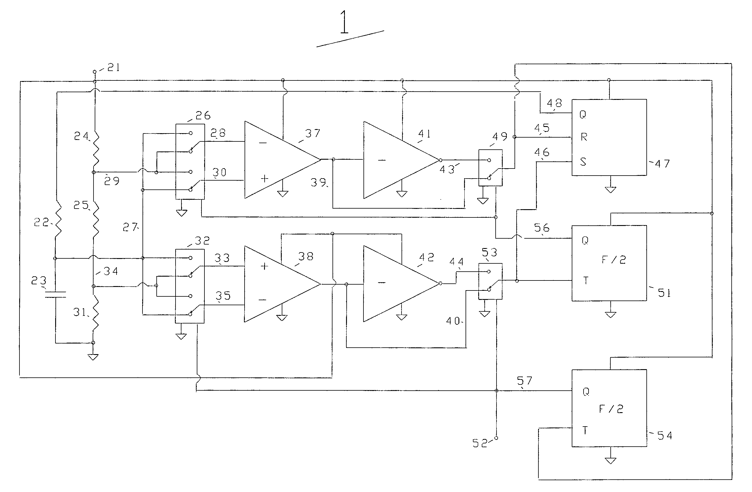
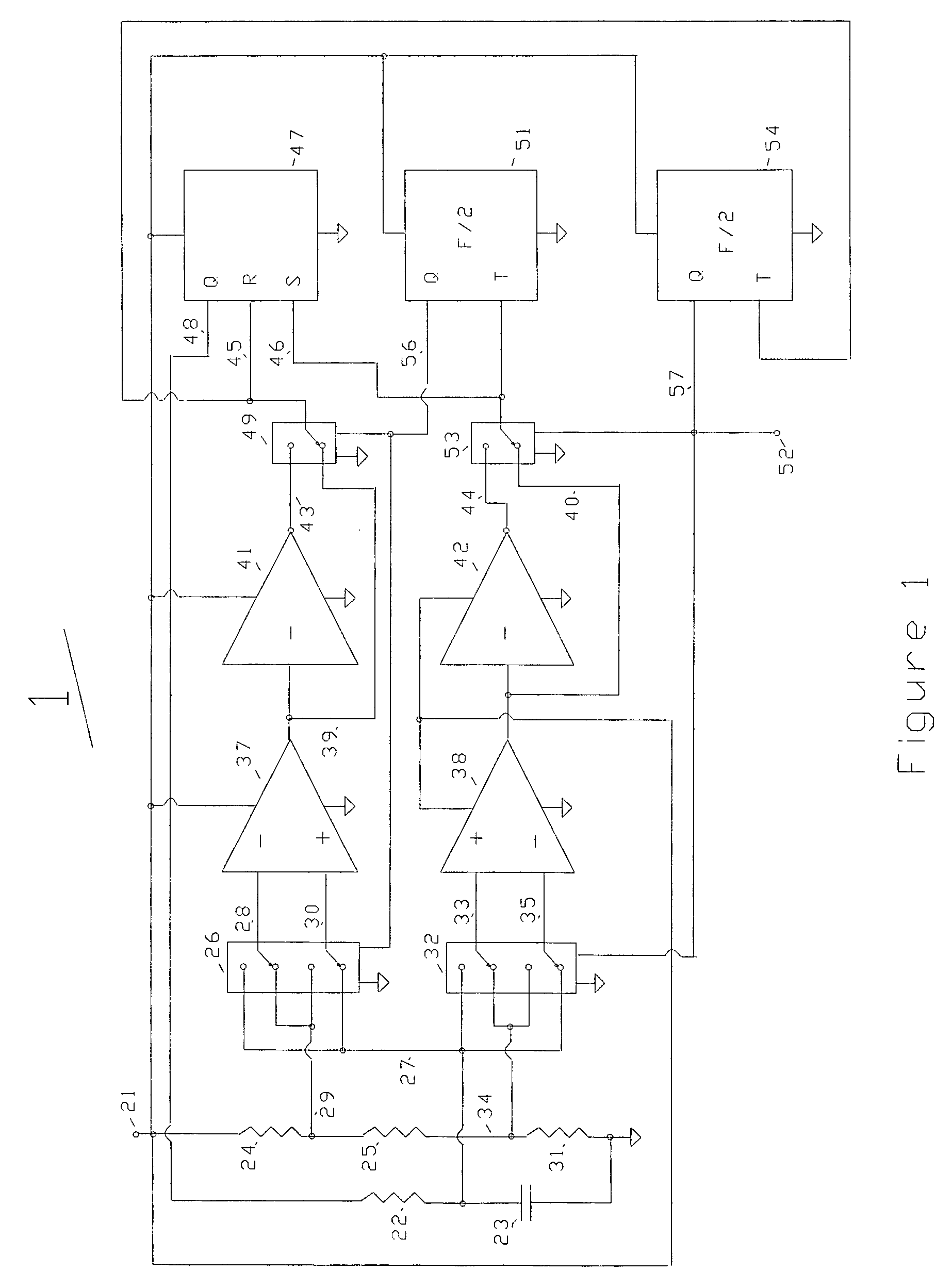
[0012] The present invention is directed to increasing the multivibrator average pulse width or frequency stability by reducing the average circuit value of the comparator offset voltage. As explained in detail below, the multivibrator contains at least one differential input comparator which is connected by switching means to timing and voltage reference circuits.

[0013]FIG. 1 shows an exemplary astable multivibrator 1 in accordance with an embodiment of the present invention. However, this invention may be applied to any multivibrator that uses one or more differential input comparators. The DC input voltage is applied to terminal 21 and powers comparators 37 and 38, inverters 41 and 42, R S flip flop 47, and frequency dividers 51 and 54. The multivibrator 1 output signal is at terminal 52. Switching means 26, 32, 49, and 53 may use relays or well known transistor circuits to accomplish the function.

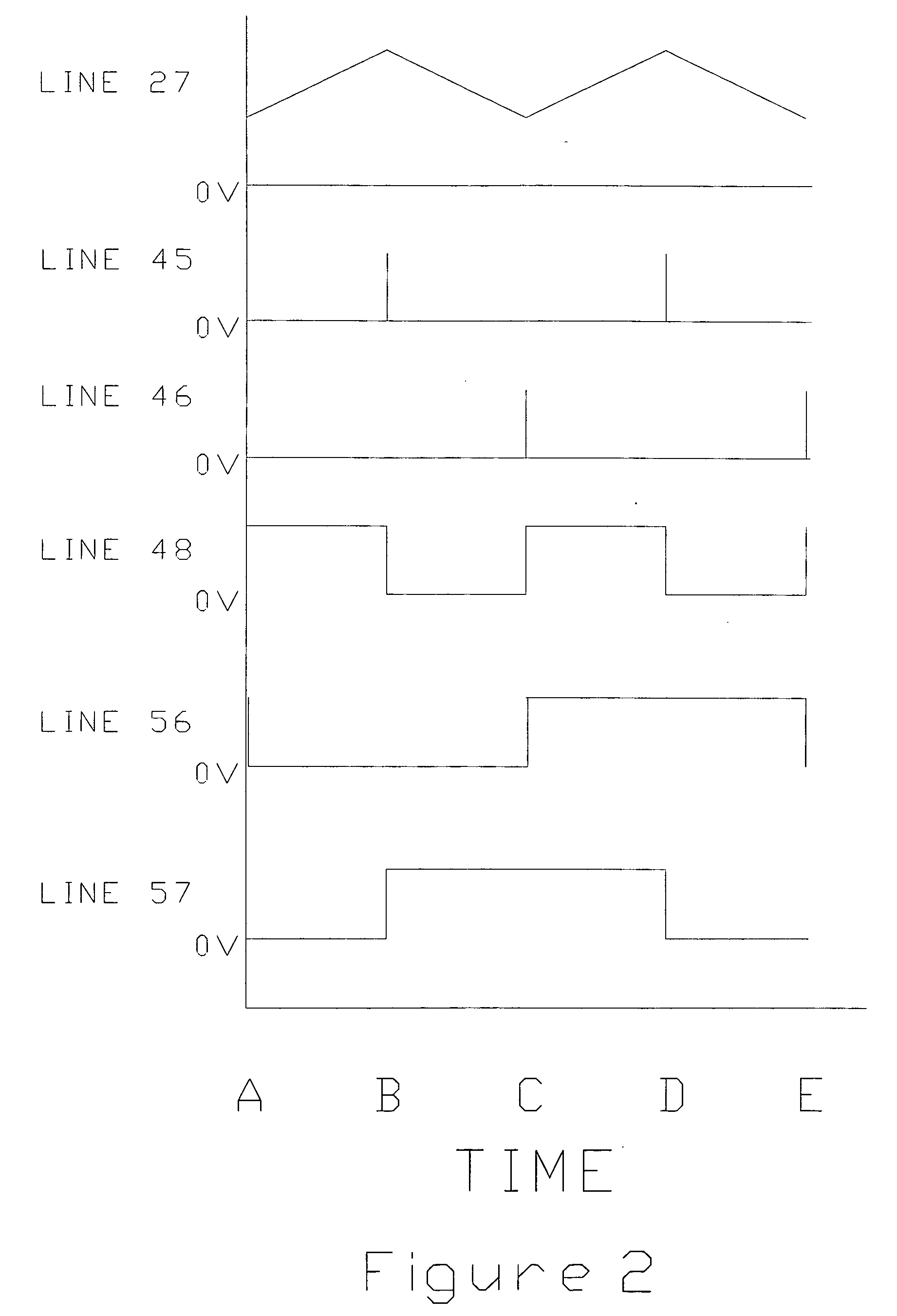
[0014] Referring also to FIG. 2, at time A line 48 goes high (essentially equal t...


PUM


Abstract

This invention relates to monostable and astable multivibrators in which the pulse width or frequency stability, respectively is increased by reducing the effect of the comparator input offset voltage. The reduction is accomplished by alternately reversing the input connections to the comparator.

Description

CROSS-REFERENCE TO RELATED APPLICATIONS [0001] The benefits of filing this invention as Provisional application for patent “MULTIVIBRATOR WITH REDUCED AVERAGE OFFSET VOLTAGE”, U.S. PTO 60 / 652,812 filed Feb. 15, 2005 by Fred Mirow are claimed.BACKGROUND ART [0002] One of the problems associated with multivibrators is that its comparator switching transition level is very sensitive to changes in ambient temperature and power supply voltage. This change causes the multivibrator to have variations in the pulse duration time or oscillation frequency. To reduce this instability some form of compensation is necessary. One of the methods used is to use a FET as a resister to control the charging time of a capacitor. The FET resistance value is controlled by a temperature dependent voltage, which varies to maintain a constant capacitor charging time. This is described in U.S. Pat. No. 4,547,749 issued to Clinton Kuo. Another method is to use a constant current source circuit, which is design...

Claims


Application Information

Patent Timeline
Patent Type & Authority Applications(United States)
IPC IPC(8): H03K3/06
CPCH03K3/0231
Inventor MIROW, FRED
Owner MIROW FRED
Why Eureka
Try Eureka