Layer cutting apparatus

a cutting device and sleeve technology, applied in the direction of metal working devices, baking articles cutting/slicing, manufacturing tools, etc., can solve the problems of large and cumbersome devices, high labor intensity, and extreme care of the above-mentioned devices, and achieve the effect of safe, effective and efficien

Inactive Publication Date: 2006-08-24
GENERAL MILLS MARKETING INC
View PDF15 Cites 3 Cited by
  • Summary
  • Abstract
  • Description
  • Claims
  • Application Information

AI Technical Summary

Benefits of technology

[0006] A primary object of the invention is to provide a layer cutter that is safe, effective and efficient in the setting of a home kitchen, or commercial foodservice operation, such as an institutional kitchen or bakery.
[0007] Another object of the invention is to provide a layer cutting device that is capable of smooth and quiet operation that does not require a source of electric power.
[0008] It is another object of the invention to provide a layer cutting apparatus that is capable of cutting layers into food products that are firm enough to maintain a distinct shape.

Problems solved by technology

This technique is labor intensive and often requires extreme care to avoid injuries to kitchen personnel.
While these devices fulfill their particular objectives and requirements, the aforementioned devices are large and cumbersome.
Accordingly, they tend to consume significant space in commercial facilities.
Therefore, known layer-cutters are not always adaptable to existing layouts.

Method used


Image

  • Layer cutting apparatus
  • Layer cutting apparatus
  • Layer cutting apparatus

Examples


Embodiment Construction

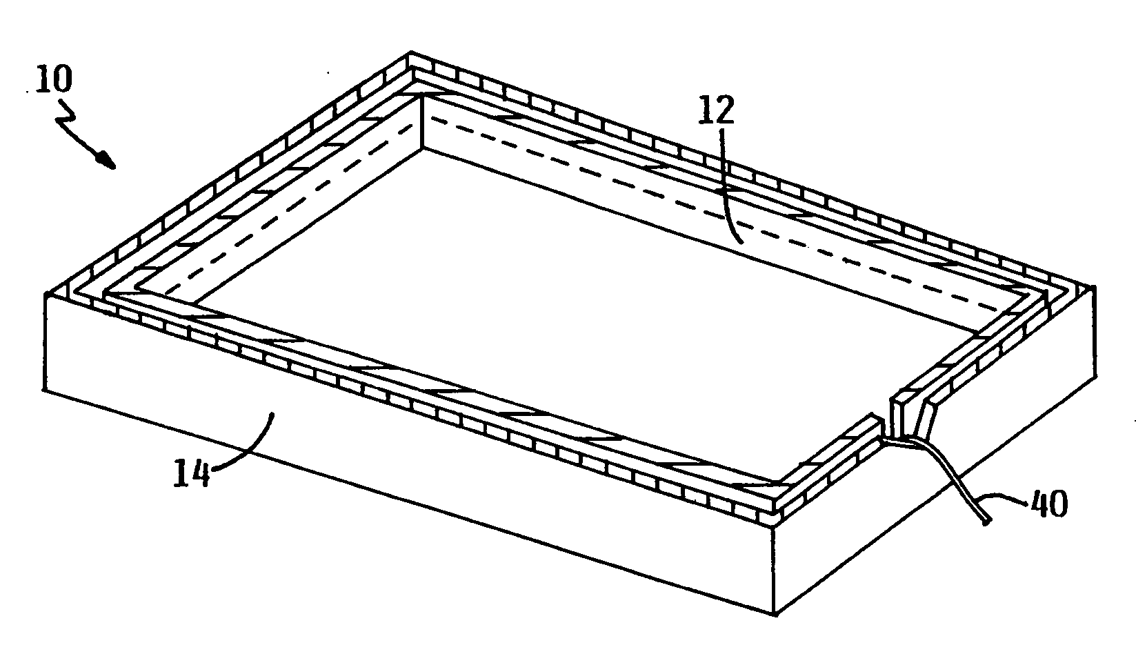
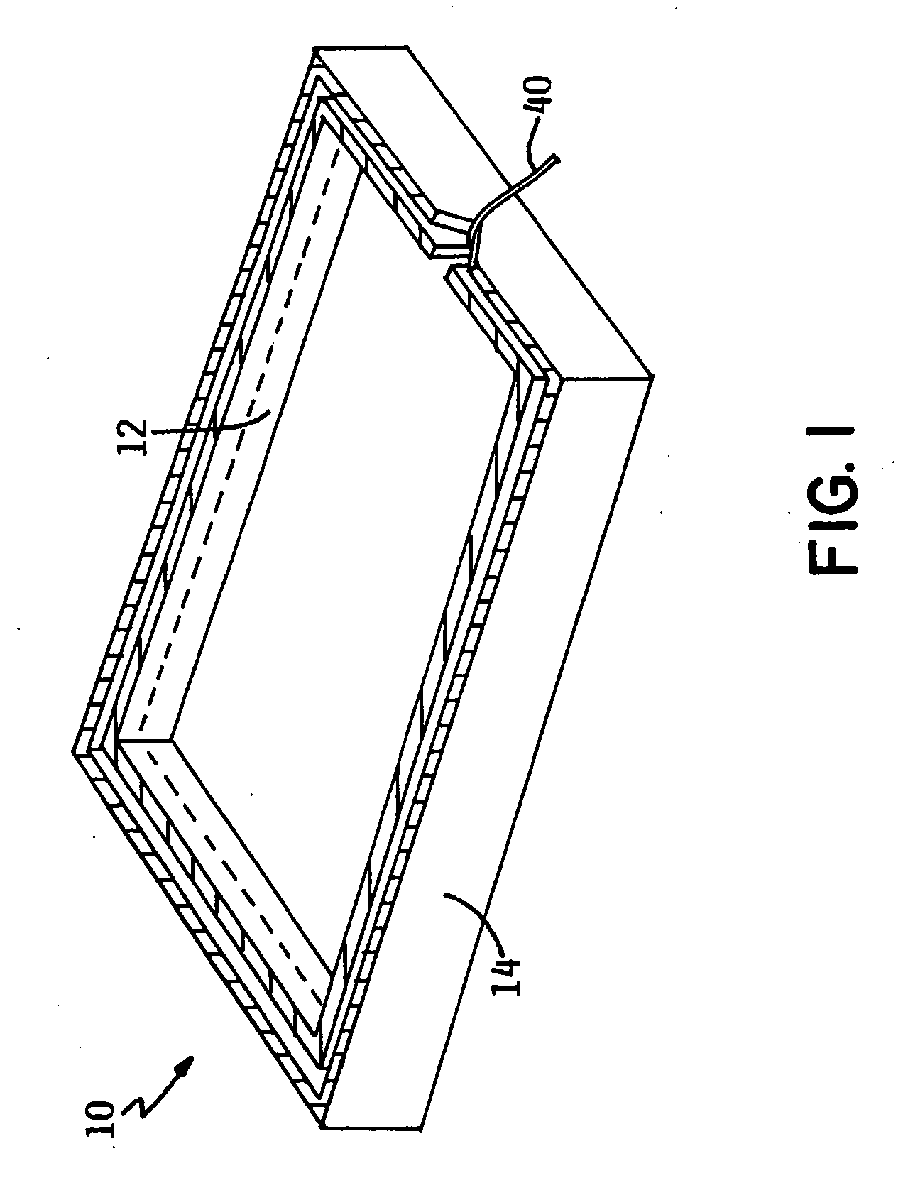
[0040] With reference to FIGS. 1 through 3, the cake-layer cutting apparatus 10 embodying the principles and concepts of the present invention will be described. Apparatus 10 includes sleeve 12 and tray 14. Sleeve 12 is configured to fit inside the inner periphery of tray 14 as shown.

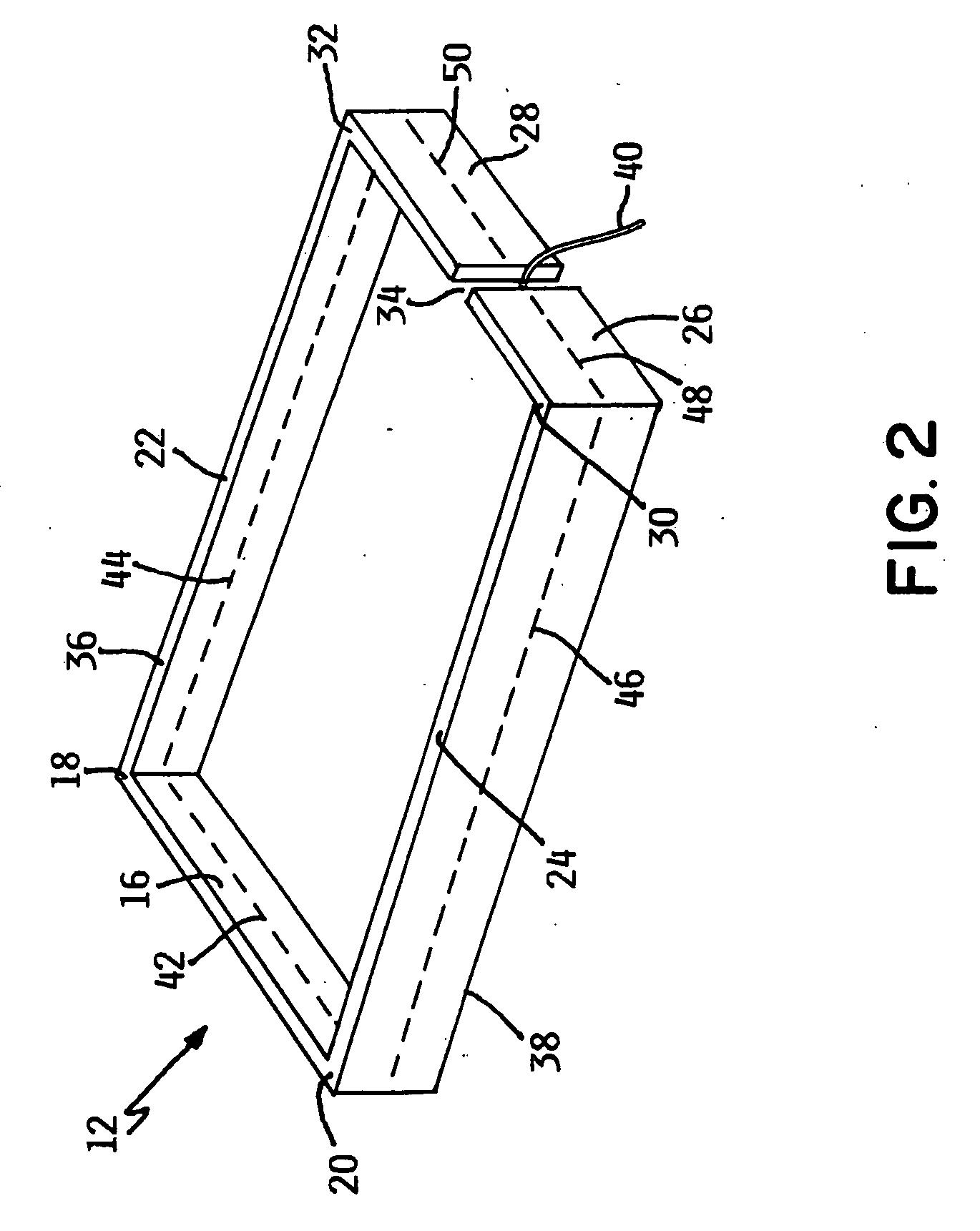
[0041] Sleeve 12 includes an elongated first side 16 terminating at a first corner 18 and a second corner 20. A second side 22 extends from first side 16 at first corner 18. Second side 22 terminates at third corner 32. Similarly, a third side 24 extends from first side 16 at second corner 20. Third side 24 terminates at fourth corner 30. Panel 26 extends from third side 24 at fourth corner 30. Panel 28 extends from second side 22 at third corner 32. Aperture 34 defines the area between panel 26 and panel 28.

[0042] Sleeve 12 includes a top edge 36 and a bottom edge 38. In FIG. 2, top edge 36 is shown parallel to bottom edge 38 although this configuration is not necessary to the invention. Cutting line...


PUM

PropertyMeasurementUnit
temperaturesaaaaaaaaaa
distanceaaaaaaaaaa

Abstract

A layer cutting apparatus comprising a tray having an interior defined by a bottom and sidewall. A sleeve is at least partially disposed in the interior of the tray and a cutting line is attached to the sleeve. The cutting line is configured to be removed from the sleeve by pulling the line away from the tray at one point of the sidewall.

Description

CROSS REFERENCE TO RELATED APPLICATIONS [0001] This application claims priority to U.S. Provisional Patent Application Ser. No. 60 / 655,211, filed Feb. 22, 2005, entitled “LAYER CUTTING APPARATUS”, which is incorporated herein by reference.FIELD OF THE INVENTION [0002] The invention relates generally to layer cutting assemblies. More particularly, the invention relates to a layer cutting tray and sleeve apparatus for allowing a user to slice layers of baked goods accurately and evenly. BACKGROUND OF THE INVENTION [0003] During the commercial preparation of food products, especially products for the bakery or foodservice industries, it is often desirable to cut a cake or other product into some predetermined form or shape. For example, in the case of frozen cakes, it is common for a commercial kitchen or bakery to employ hand laborers to slice the cakes into layers for further decorating or sale. [0004] In many kitchens, a large knife is used to separate frozen cakes into layers. This...

Claims


Application Information

Patent Timeline
Patent Type & Authority Applications(United States)
IPC IPC(8): B26B3/00
CPCA21C15/04B26B27/002B26D1/547Y10S83/932Y10T83/04Y10T83/424Y10T83/472Y10T83/9292
Inventor BAETEN, JAMES R.LITTLE, VANESSA L.LITTLEFIELD, KARALYN R.YUNGNER, MARK W.ZOSS, ROBERT A.
Owner GENERAL MILLS MARKETING INC
Why Eureka
Try Eureka