Resin drying method and apparatus

a technology of resin drying method and apparatus, which is applied in the direction of drying machines with progressive movements, lighting and heating apparatus, and granular material drying, etc., can solve the problems of hydrophilic resins absorbing moisture, unable to be properly processed, and leaving bubbles and other imperfections in the finished produ

Inactive Publication Date: 2006-08-24
MAGUIRE STEPHEN B
View PDF84 Cites 15 Cited by
  • Summary
  • Abstract
  • Description
  • Claims
  • Application Information

AI Technical Summary

Benefits of technology

[0017] The canister is further preferably adapted to effectuate material dispensing upon contact by a downwardly moving rod of a top-mounted pneumatic piston-cylinder combination moving an open centered valve member into position at the bottom of the canister for maximum flow downwardly therethrough. When open, the valve permits relatively unimpeded, free downward flow of material out of the canister.

Problems solved by technology

These hydroscopic resins absorb moisture and cannot be properly processed by molding or extrusion until dried.
If processed before dry, moisture in the plastic boils at or approaching the high plastic molding or extrusion process temperatures, leaving bubbles and perhaps other imperfections in the finished product.
Some granular resin materials are extremely hydroscopic and become unprocessable by molding or extrusion in ten minutes or less after exiting a dryer, due to the rapid absorption of moisture by the granular resin material.
During the drying process, the granular resin material cannot be permitted to soften, since it becomes unmanageable.
Once granular resin material begins to soften, at temperatures above the boiling point of water, the granular resin material pellets stick together in lumps or even melt into useless masses of solid plastic, making it impossible to further process the resin material into a useful article.

Method used


Image

  • Resin drying method and apparatus
  • Resin drying method and apparatus
  • Resin drying method and apparatus

Examples


second embodiment

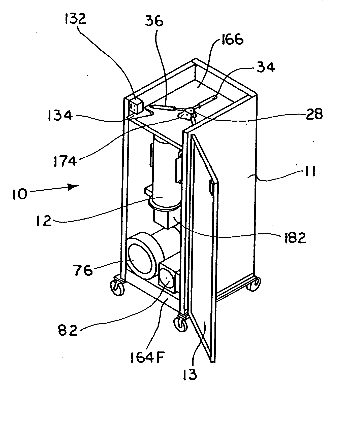
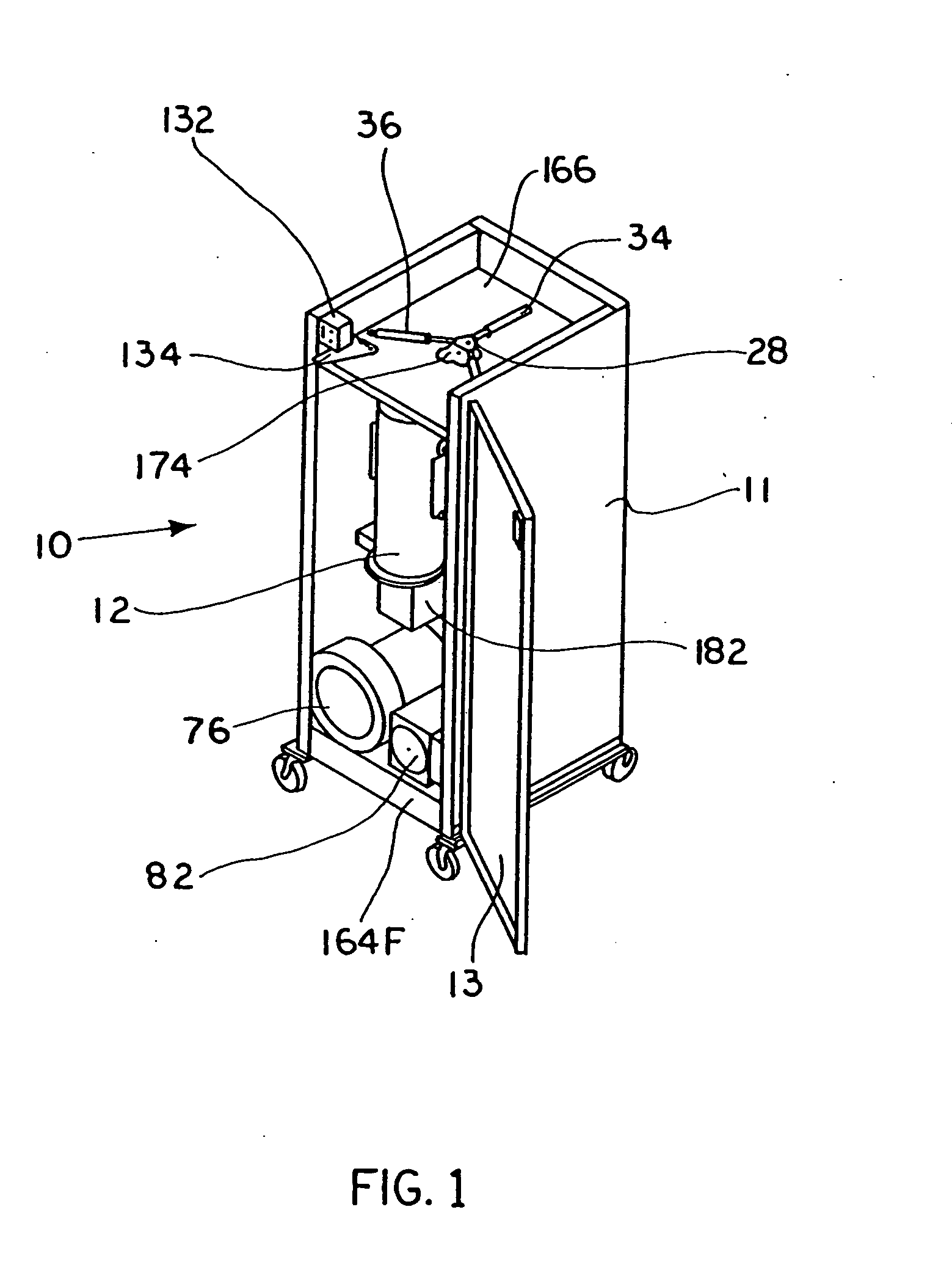
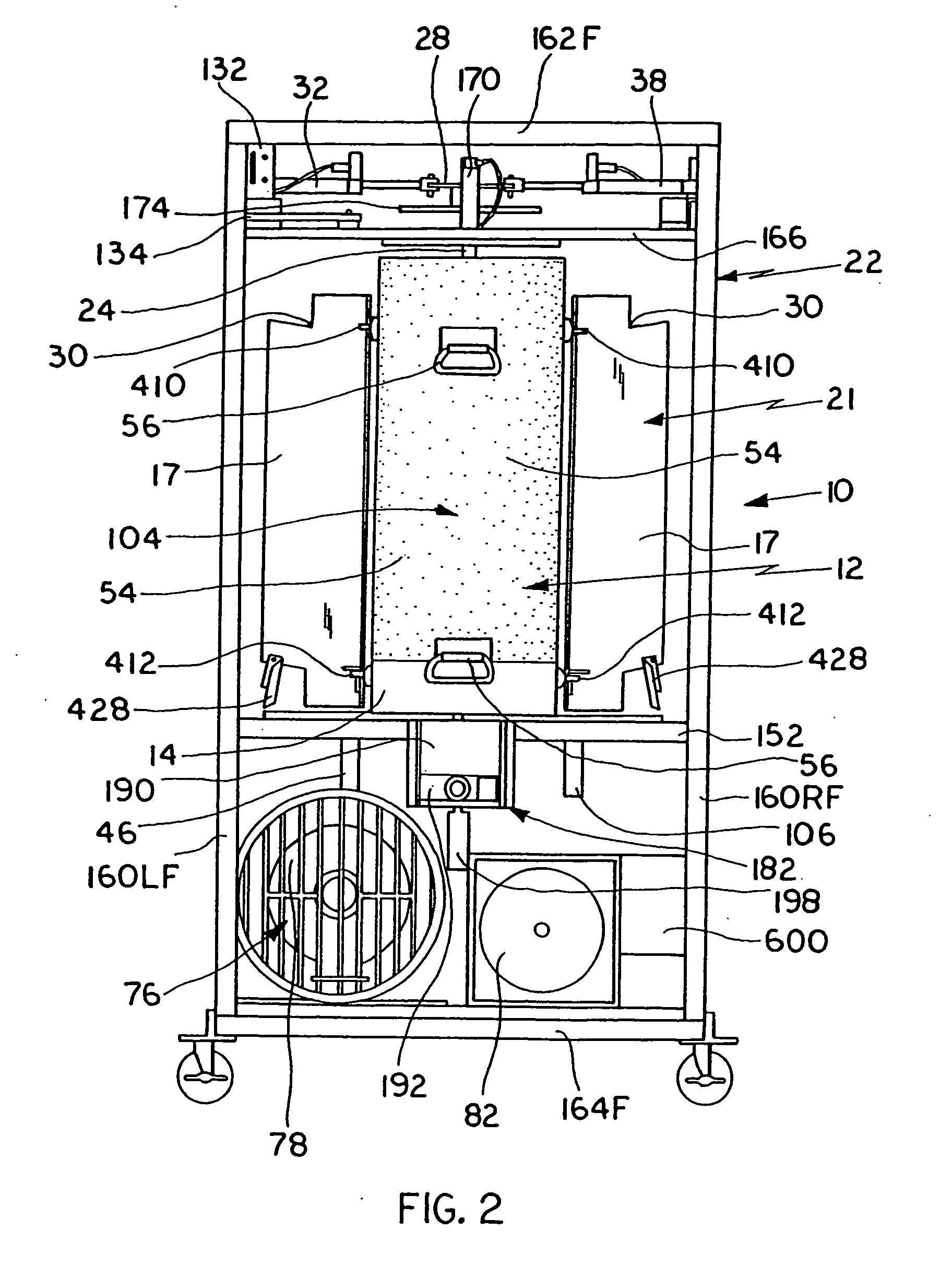
[0165]FIG. 13 schematically depicts a vacuum dryer embodying aspects of the invention where the vacuum dryer is designated generally 200. A material supply container 202 or equivalent structure is provided as indicated schematically at the top of FIG. 13; material supply container 202 need not be a part of vacuum dryer 200.

[0166] A preferably tubular material feed line 224 or equivalent structure leads out of material supply 202, preferably downwardly, and connects to a material flow control valve or equivalent structure depicted schematically as 204 in FIG. 13.

[0167] Material flow control valve 204 provides material to either of two material feed lines 226, 226A or equivalent structure which lead to respective ones of first and second material processing chambers 210, 212 or equivalent structure, both of which are illustrated as vertically oriented cylindrical processing chambers in FIG. 13. Other geometric configurations and shapes may also be used.

[0168] First and second materi...

third embodiment

[0179] a vacuum dryer manifesting aspects of the invention is illustrated schematically in FIG. 14 with the vacuum dryer being designated generally 300 and including a material processing chamber designated generally 302.

[0180] A material supply container or equivalent structure is designated generally 304 and serves as a storage receptacle for granular or powdery material requiring drying; material supply container 304 need not be a part of dryer 300.

[0181] Material processing chamber 302 or equivalent structure is preferably equipped with a preferably sealing lid designated generally 306 and positioned to close an inlet end 326 of processing chamber 302 or equivalent structure. Sealing lid 306 is preferably moved by a preferably pneumatic actuating cylinder 308 connected to sealing lid 306 by a suitable pivoting arm 310. Upon actuation of cylinder 308, sealing lid 306 moves into position to seal inlet end 326 of processing chamber 302.

[0182] Granular resin or powdery material re...


PUM

PropertyMeasurementUnit
depthaaaaaaaaaa
angleaaaaaaaaaa
timeaaaaaaaaaa

Abstract

A low pressure dryer for granular or powdery material includes a plurality of canisters rotatable about a common vertical axis serially among material heating, vacuum drying and material inventory discharge positions; pneumatic piston-cylinder means for rotating the canisters about said axis among said heating, vacuum drying and inventory discharge positions; means for heating contents of a canister at said heating position; means for sealing and drawing vacuum within a canister at said vacuum drying position and means for selectably permitting downward flow of dried granular or powdery material out of a canister at said discharge position where said canisters move collectively and unitarily one with another.

Description

CROSS-REFERENCE TO RELATED PATENT APPLICATION [0001] This patent application is filed under 35 USC 120 as a division and claiming the benefit of the priority of co-pending U.S. patent application Ser. No. 09 / 883,837, entitled “Low Pressure Dryer”, filed 18 Jun. 2001 in the name of Stephen B. Maguire, which in turn claims priority under 35 USC 119 of provisional U.S. patent application Ser. No. 60 / 212,112, entitled “Low Pressure Dryer”, filed 16 Jun. 2000 in the name of Stephen B. Maguire, the benefit of the priority of which is also claimed for this application under 35 USC §§ 119 and 120.BACKGROUND OF THE INVENTION [0002] 1. Field of the Invention [0003] This invention relates to drying granular or powdery material, preferably granular resin material, prior to processing thereof into intermediate or finished products, preferably by extrusion or molding. [0004] 2. Description of the Prior Art [0005] Plastic resins are initially granular materials and are produced in pellets. These p...

Claims


Application Information

Patent Timeline
Patent Type & Authority Applications(United States)
IPC IPC(8): F26B13/30B29C47/76F26B5/06A21C3/02B01F15/00B29B13/06B29C31/06B29C48/76F26B5/04F26B17/12
CPCB01F15/00805B29B13/065B29C31/061F26B5/042F26B17/128F26B2200/08B29B7/005B29B9/16F26B5/04B01F35/453
Inventor MAGUIRE, STEPHEN B.
Owner MAGUIRE STEPHEN B
Why Eureka
Try Eureka