Magnetic recording head and method for high coercivity media, employing concentrated stray magnetic fields

a magnetic recording and high coercivity technology, applied in the direction of magnetic recording, recording/reproducing/erasing methods, assembling head elements, etc., can solve the problems of insufficient utilization of tapes with coercivity higher than about 3 koe, progress of this technology, and closer operation, so as to achieve high coercivity and linear density leap forward without increasing power consumption, and high gradient

Inactive Publication Date: 2006-08-24
TANDBERG DATA STORAGE
View PDF14 Cites 20 Cited by
  • Summary
  • Abstract
  • Description
  • Claims
  • Application Information

AI Technical Summary

Benefits of technology

[0014] An object of the present invention is to provide a magnetic write head that produces a high write field with a high gradient allowing a significant leap forward in media coercivity

Problems solved by technology

Attempting to merely scale down mechanical dimensions, however, results in operations closer to thermal instability of the magnetization, known as the “Superparamagnetic Limit”.
The challenge is to create a strong enough magnetic field with a high enough field gradient to write a high-density signal on such a medium.
Therefore tape with coercivity higher than about 3 kOe cannot be properly utilized.
Impeding the progress of this technology has been noise from the SUL.
This is a clear drawback

Method used


Image

  • Magnetic recording head and method for high coercivity media, employing concentrated stray magnetic fields
  • Magnetic recording head and method for high coercivity media, employing concentrated stray magnetic fields
  • Magnetic recording head and method for high coercivity media, employing concentrated stray magnetic fields

Examples


Embodiment Construction

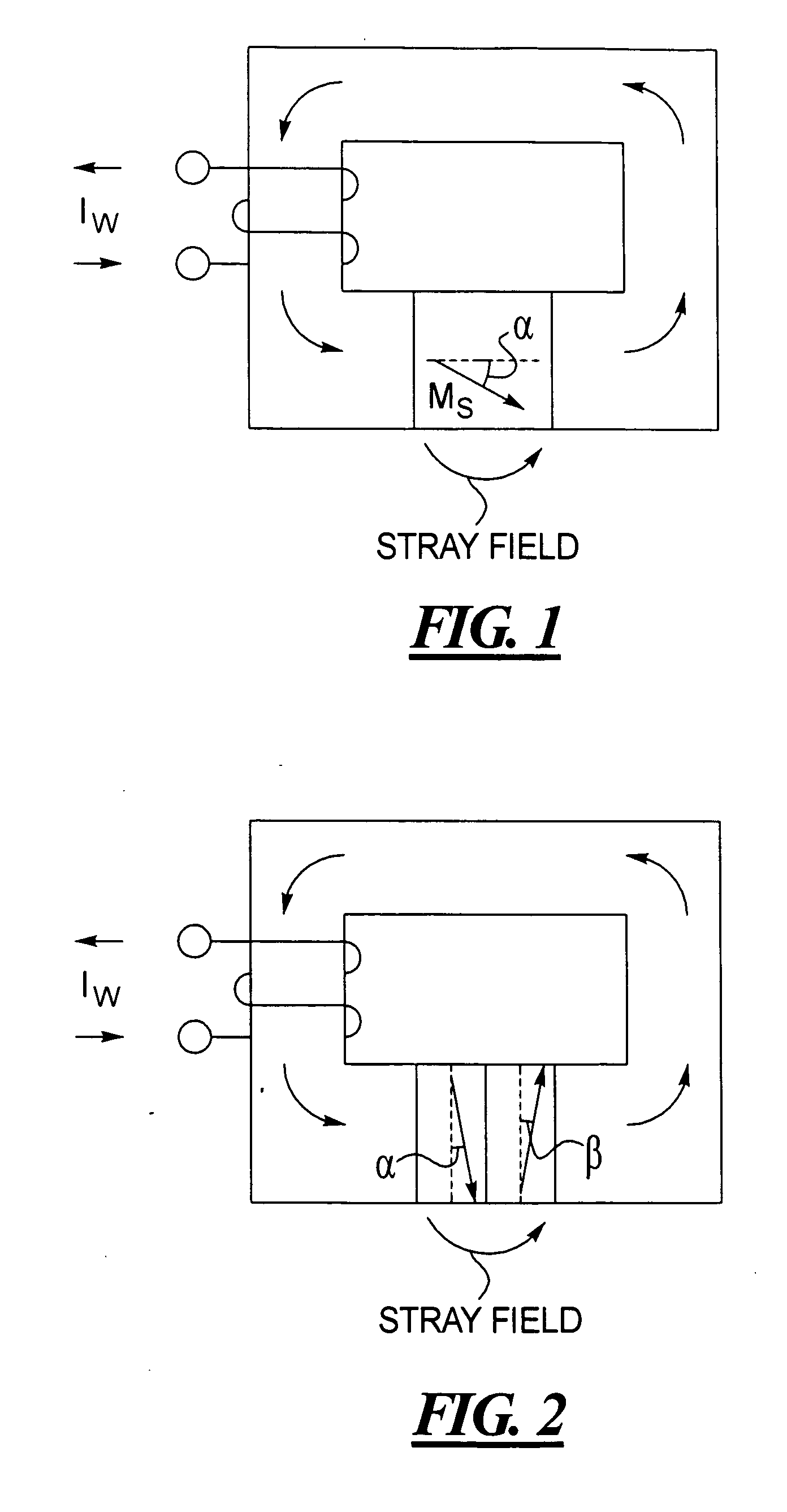
[0038]FIG. 1 illustrates the simplest embodiment of a write head for longitudinal recording using a permanent magnet to boost the stray field. A single permanent magnet with a magnetization vector at an angle α with the ABS is placed in the gap of a conventional write head core. The angle α is chosen so as to obtain optimal recording properties, i.e. the strongest, highest gradient combined field from the permanent magnet and the soft magnetic circuit.

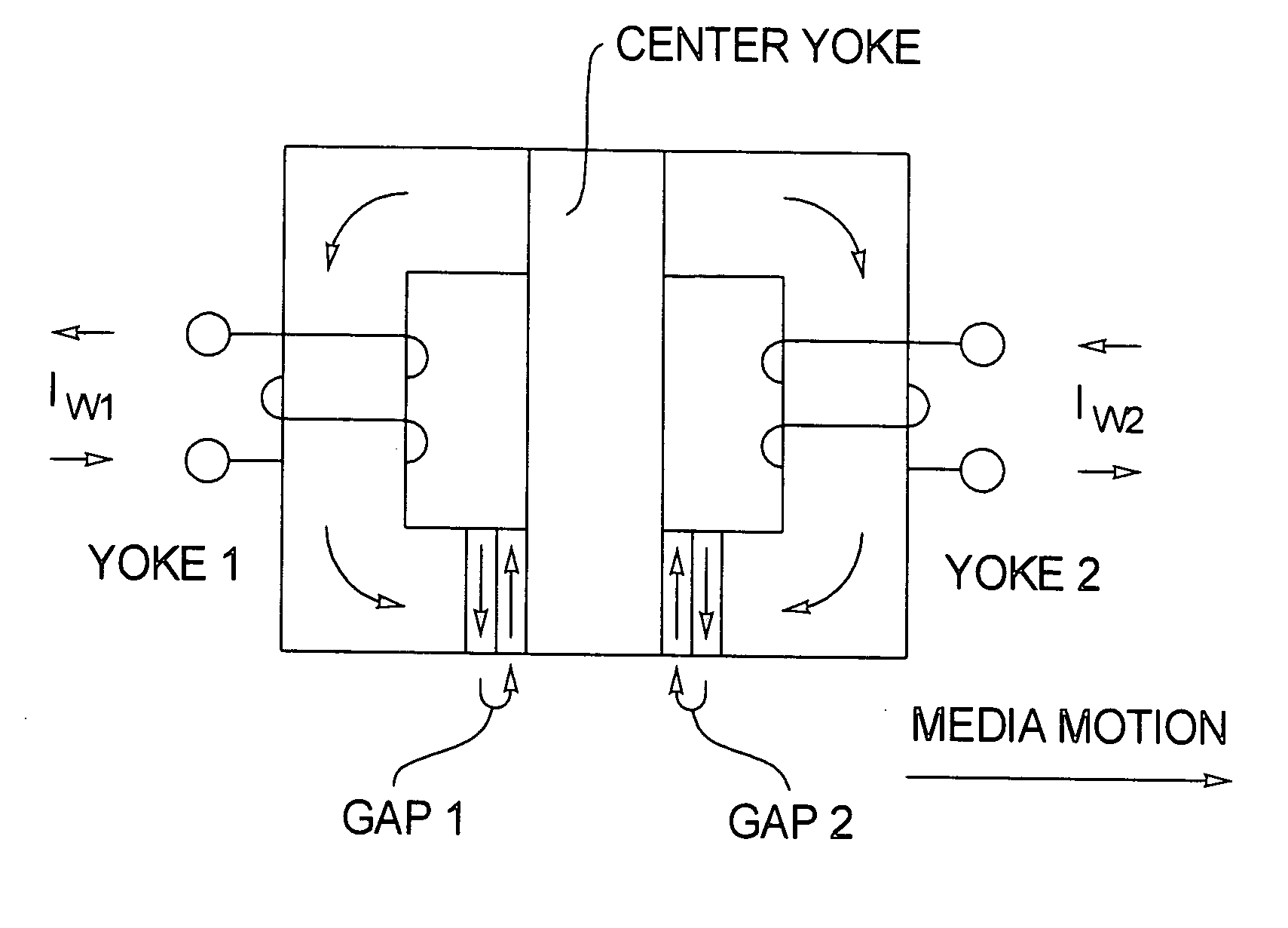
[0039] In accordance with the invention, a much stronger, higher gradient stray field can be obtained from a combination of two permanent magnets with essentially anti-parallel magnetization vectors. FIG. 2 shows in principle how the two magnets M1 and M2 are located in the gap of a traditional write head core. The directions of their magnetization and also the stray field out of the gap are shown with arrows. Also a write winding with write current Iw and the corresponding field in the core is depicted. This arrangement is for longit...


PUM


Abstract

In methods and arrangements for concentrating stray magnetic fields, a pair of permanent magnets is employed in combination with a magnetic flux circuit, the permanent magnets in the pair having respective magnetizations that are oriented oppositely to each other. The permanent magnets produce a stray magnetic field that adds to a magnetic field produced by the magnetic flux circuit.

Description

BACKGROUND OF THE INVENTION [0001] 1. Field of the Invention [0002] The present invention is directed to arrangements and methods suitable for use in magnetic recording, test and measurement equipment and other purposes, employing concentrated stray magnetic fields. [0003] 2. Description of the Prior Art [0004] During recent years there has been a continuous drive towards higher storage capacity and correspondingly faster data transfer rates. For magnetic storage devices the path to higher storage density per area is through the development of media with increasingly smaller magnetic grains. [0005] Attempting to merely scale down mechanical dimensions, however, results in operations closer to thermal instability of the magnetization, known as the “Superparamagnetic Limit”. [0006] Changing to grains made of materials that have higher crystalline magnetic anisotropy moves this limit. This suggests the use of higher magnetic coercivity materials, which are readily available. The challe...

Claims


Application Information

Patent Timeline
IPC IPC(8): G11B5/127G11B5/00G11B5/02H01F13/00
CPCG11B5/02G11B5/127G11B5/1272G11B5/1278G11B2005/0029
Inventor SAMOFALOV, VLADIMIR NIKOLAEVICHLUB'YANIY, LEONID ZAKHAROVICHIL'YASHENKO, EVGENIY IVANOVICHRAMSTAD, AUDUN
Owner TANDBERG DATA STORAGE
Why Eureka
Try Eureka