
Thermoacoustic engine-generator

a generator and engine technology, applied in the direction of generators/motors, machines/engines, lighting and heating apparatus, etc., can solve the problems of limited power output of standing wave systems, large output work, and low power density, so as to reduce short-circuit thermal conduction, minimize thermal losses, and limit the path of energy exchange

Inactive Publication Date: 2005-06-28
FELLOWS RES GRP INC
View PDF4 Cites 44 Cited by
  • Summary
  • Abstract
  • Description
  • Claims
  • Application Information

AI Technical Summary

Benefits of technology

The design significantly increases power density by amplifying thermal energy gradients and sonic velocity, reducing the size of heat exchangers, and maintaining a desired temperature differential, resulting in a more efficient energy conversion process.

Problems solved by technology

The most significant problem with prior art thermoacoustic engines and refrigerators is that they have a very low power density.
They are typically much larger and more massive for the amount of output work they produce, than other types of engines and refrigerators.
The power output of standing wave systems is limited by the inherent physical characteristics, to wit; standing wave systems rely on the forward-going wave being inverted and reflected uniformly back along the resonator at nearly the same propagation velocity.
If too much energy is extracted from the forward-going wave in the cold-side heat exchanger, the propagation velocity of the return wave is changed and the forward-going wave and the return wave will be out of phase and will interfere with each other.
This adds impedance to the cycle and tends to damp the oscillation.
This inherent characteristic severely limits the quantity of energy per cycle that is available to perform useful work, resulting in large engines with low power density.
Where the desirable state of operation in most thermoacoustic engines is such that the mass of the working fluid resides in a static state, with the energy transport confined to pressure impulses (acoustic waves) that transit the working fluid, streaming is considered as an impedance; an undesirable effect.
This is typically problematic only in traveling-wave engines, where the energy impulses travel in only one direction.

Method used


Image

  • Thermoacoustic engine-generator
  • Thermoacoustic engine-generator
  • Thermoacoustic engine-generator

Examples


Embodiment Construction

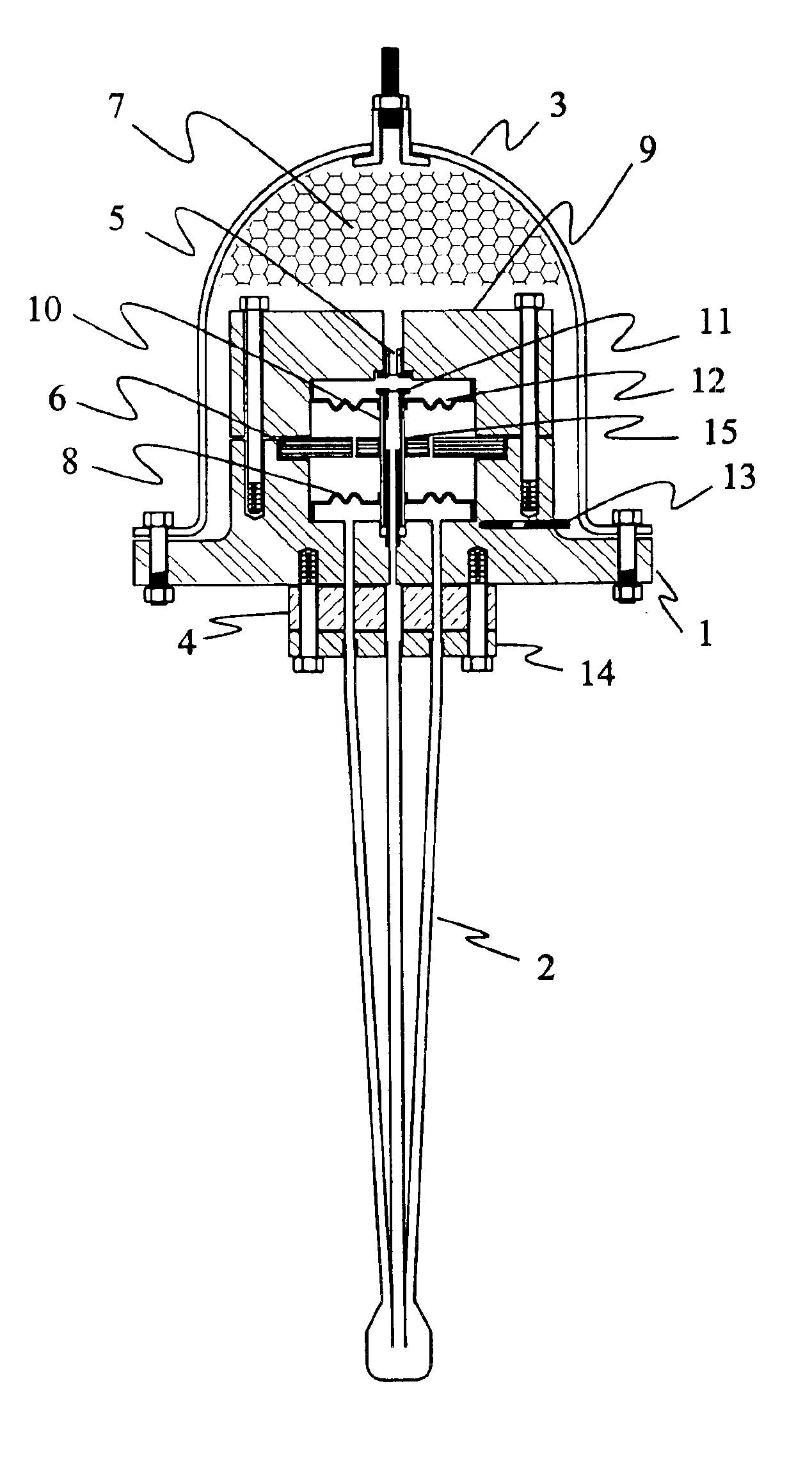
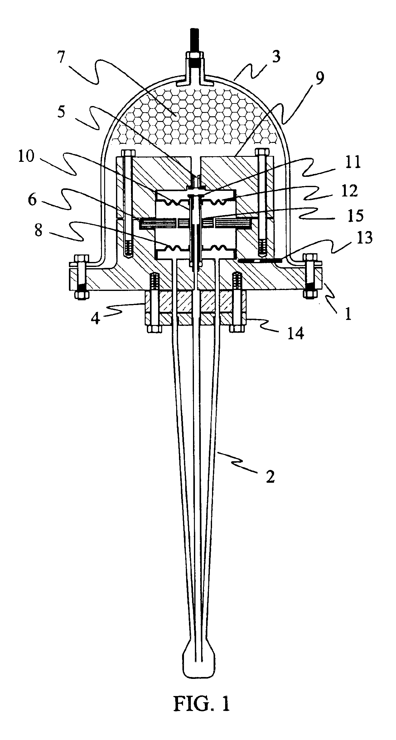
[0049]The TAC Engine-Generator will be described with reference to drawings that are not to scale. In the drawing figures, the reference character 2 indicates the component referred to as HX sub h in the specification, and the reference character 7 indicates the component referred to as HX sub c in the specification.

[0050]With respect to FIG. 1; the thermal break 4 is a thermal insulating means, preferably a material such as pressed fiber, ceramic or plastic, although other materials can be used, even metals that are poor conductors of heat. The purpose of the thermal break 4 is to minimize short-circuit thermal conduction between the first heat exchanger-waveguide 2, and the generator housing 1 in order to reduce conductive losses and increase thermal-to-electric conversion efficiency. Maximum efficiency depends upon maintaining the widest possible thermal gradient between the first heat exchanger-waveguide 2 and the second heat exchanger means 7. The first heat exchanger-waveguide...


PUM


Abstract

A thermoacoustic engine-generator that converts waste heat into electrical power. Thermal energy is converted to useful work via temperature-pressure amplification of periodic acoustic traveling waves in a compressible working fluid which cause the armature of a linear alternator to reciprocate and produce alternating current electrical energy. An external oscillator initiates reciprocating motion in the armature of a linear alternator. The armature is a combination fluid pump and fluid motor as well as the induction armature of a linear alternator. The pump end of the armature generates an acoustic traveling wave with each cycle of the armature. The traveling wave enters a waveguide-heat exchanger and is amplified in temperature, pressure and propagation velocity by thermal conduction of energy through the wall of the waveguide. The amplified traveling wave acts upon the opposite end of the armature, causing it to reciprocate within the magnetic field windings of the generator, and generate an electrical current as well as a new acoustic traveling wave. When the operating temperature gradient is attained across the hot and cold heat exchangers, the thermoacoustic engine-generator becomes acoustically resonant and self-regenerative, and will continue to operate as long as the thermal gradient is maintained. The theoretical conversion efficiency is dependent on the thermal gradient, and is 63% of Carnot.

Description

[0001]This application claims benefit of U.S. Provisional 60 / 418,258 filed Oct. 15, 2002.BACKGROUND OF THE INVENTION[0002]The subject invention originates from twenty-two years research by the inventor, into engines and resonators that operate on the principles of thermoacoustic physics. For purposes of this application for patent, the term “thermoacoustic” refers to traveling energy impulses, normally detected as pressure fluctuations, propagating along velocity vectors that move thermal energy through an elastic medium that is typically a compressible working fluid. For purposes of this application for patent, thermoacoustic energy includes both shockwaves (supersonic and hypersonic pressure waves) and sound waves (pressure waves traveling at the sonic velocity of the working fluid under locally extant conditions).[0003]The research background data in heat, acoustic wave phenomena and gas mechanics includes the shock tube research performed by government and institutional scientis...

Claims


Application Information

Patent Timeline
Patent Type & Authority Patents(United States)
IPC IPC(8): F02G1/00F02G1/043H02K7/18
CPCF02G1/0435H02K7/1876F02G2243/54
Inventor FELLOWS, OSCAR LEE
Owner FELLOWS RES GRP INC
Learn More