Fill material for direct-contact heat/mass exchangers

a technology of filling material and heat/mass exchanger, which is applied in the field of neutral materials to achieve the effect of avoiding the effect of unnecessarily high friction on the movement of the fluid, and reducing the size of the fluid path

Inactive Publication Date: 2015-02-19
BARTON SEAN ANDERSON
View PDF17 Cites 52 Cited by
  • Summary
  • Abstract
  • Description
  • Claims
  • Application Information

AI Technical Summary

Benefits of technology

[0017]The purpose of the fill material for direct contact heat / mass exchangers of the present invention is to alleviate the dysfunctions of current DC heat exchangers, to allow for DC heat exchangers with small fluid pathways that do not flood, where the fluid / fluid interface is stably anchored in the desired location, and where the frictions on the movements of the fluids are not unnecessarily high, thus allowing for yet greater reductions in fluid path size leading to even higher densities of heat exchange.
[0018]The preferred embodiment for contoured heat / mass exchange of air and water in an evaporator or condenser is shown in the FIGS. 11 and 12. The larger volume is devoted to the air because of its lower heat capacity and related larger volume flow requirements. This preferred embodiment has the following advantages. It can be produced with an additive manufacturing process that deposits linear elements of material through an extrusion nozzle (like 3D printing). The indicated angle is kept at less than 60 degrees to eliminate the need to introduce the fluids in a particular order. By arranging the fluids into volumes separated by parallel planes (similar to a plate and frame heat exchanger, not a tube and shell heat exchanger) both fluids are allowed to flow not just in one direction but in two perpendicular directions. It may be found that one of the directions provides less resistance to fluid flow. Both dimensions of flow may be used simultaneously as oblique flow is required in contoured heat exchangers. Because the fluid / fluid interface anchoring elements are staggered, they provide less resistance to and congestion of the fluid flow and allow for a greater area fraction of open aperture between the fluids (providing more heat / mass exchange, less friction, and less material cost) while still providing mechanical structure.
[0019]The preferred embodiment for non-countered DC heat exchange of water and some common oil is likely similar to the hexagon-triangle geometry shown in FIGS. 5 and 6. While this geometry does not allow for contoured heat exchange because the fluid pathways are in a closed-cell arrangement, contours are not needed for oil / water because the heat capacity of the oil and water are both sufficiently independent of temperature. The hexagon-triangle geometry allows for one of the two fluids (fluid A in FIGS. 5 and 6) to have larger fluid pathways to better accommodate the low heat capacity and high viscosity of one of the fluids, in this case the oil. Additionally, the hexagon-triangle geometry does not need any structural elements that do not also serve to anchor the fluid / fluid interfaces. Thus, it may have less friction for the same heat exchange compared to the preferred embodiment for air / water.
[0020]While it is desired to provide manifolds for the distribution and recollection of the fluids, such manifolds are not required. Distribution can often be accomplished with a spray of the fluid which occupies the minority of the volume. If the heat exchanger of the current invention begins in an atmosphere of fluid A and fluid B (the minority volume fluid) is sprayed upon it, droplets of fluid B will adhere to the linear elements and grow as they collect more droplets from the spray. When the droplets have grown large enough to touch neighboring droplets, they will spontaneously combine and with their increased weight begin to move downward through the matrix of linear elements filling the channels of smaller size. In cases where volume is divided roughly equally between the two fluids and neither fluid occupies a minority volume (as in the embodiments of FIGS. 3, 7, 8, 9, and 10, spray accumulation will fill the compartments indiscriminately and is thus inadequate. In these cases manifolds are required. When the fluid A reaches the bottom of the heat exchanger it can be discharged from the heat exchanger by wicks of a wetting material of sufficient length. To reduce the amount of space needed and eliminate the need for the wicks and the maintenance, energy consumption, misting, and fluid crossover issues associated with operating sprayers, it is desired to provide manifolds that inject and extract the fluids into and out of their respective spaces in the matrix of linear elements. Such manifolds do not have to be sealed to the heat exchanger (matrix or fill material) as they must be in an IDC heat exchanger, but simply need to be in close proximity to it (almost touching or touching such that any gaps are smaller than the mesh aperture). To minimize back pressure in these distributing and collecting manifolds, especially for any fluid which requires high pumping energy, branching fluid pathways (similar to the arteries and veins in the human body) should be used. For a fluid requiring lower pumping energy, the remaining space within the manifold (the space not occupied by the high-pumping-energy fluid) is often fully adequate to facilitate the distribution and recollection of the low-pumping-energy fluid. When both fluids require high pumping energy, distributor / collectors must be of larger size to accommodate the required cross-sectional area for flow of both fluids.
[0021]Thus, the fill material for direct contact heat / mass exchangers of the present invention has many critical advances in the art. Specifically, the fill material for direct contact heat / mass exchangers is a direct contact heat exchanger fill material that has flow pathways bounded by an array of linear elements or mesh. Preexisting DC heat exchangers allow one of the two fluids to coat the mesh. Stated differently, the mesh is inside one of the fluids and does not touch the other fluid. In the fill material for direct contact heat / mass exchangers, the mesh is placed between the two fluids, so that the mesh is touching both fluids, much like the thermally-conductive fluid-impermeable barriers are placed in an IDC heat exchanger. In a conventional type DC heat exchanger, wetting surfaces are advantageous. In the fill material for direct contact heat / mass exchangers, neutrally wetting surfaces are advantageous allowing for a much greater variety of materials. The fill material for direct contact heat / mass exchangers intentionally uses surface tension and capillary action to anchor the fluid / fluid interface in a desired location. The fill material for direct contact heat / mass exchangers uses a wick or collector in direct contact with the fill material (matrix) to extract fluid without formation of large droplets. When fluid pathways become very small, even a single drop of liquid can be large enough to block a neighboring pathway for intake of the other fluid. Stated differently, when fluid pathways are very small, discharging drops of fluid inflate to inconveniently large size before becoming heavy enough to detach (forming a single drop). These drops can be large enough to block neighboring fluid intake channels. The fill material for direct contact heat / mass exchangers -uses a distributor in direct contact with the fill material (matrix) or a sprayer to place the fluids in the appropriate fluid pathways. The fill material for direct contact heat / mass exchangers uses fluid / fluid interface anchoring with a discharge system in direct contact. The interface anchoring prevents flooding and allows reduction in fluid pathway size. At smaller fluid pathway sizes the problems with discharge become more obvious. The fill material for direct contact heat / mass exchangers can direct the fluid into spaces arranged as parallel planes to permit oblique flow of the fluids.

Problems solved by technology

The larger volume is devoted to the air because of its lower heat capacity and related larger volume flow requirements.
While this geometry does not allow for contoured heat exchange because the fluid pathways are in a closed-cell arrangement, contours are not needed for oil / water because the heat capacity of the oil and water are both sufficiently independent of temperature.

Method used


Image

  • Fill material for direct-contact heat/mass exchangers
  • Fill material for direct-contact heat/mass exchangers
  • Fill material for direct-contact heat/mass exchangers

Examples


Embodiment Construction

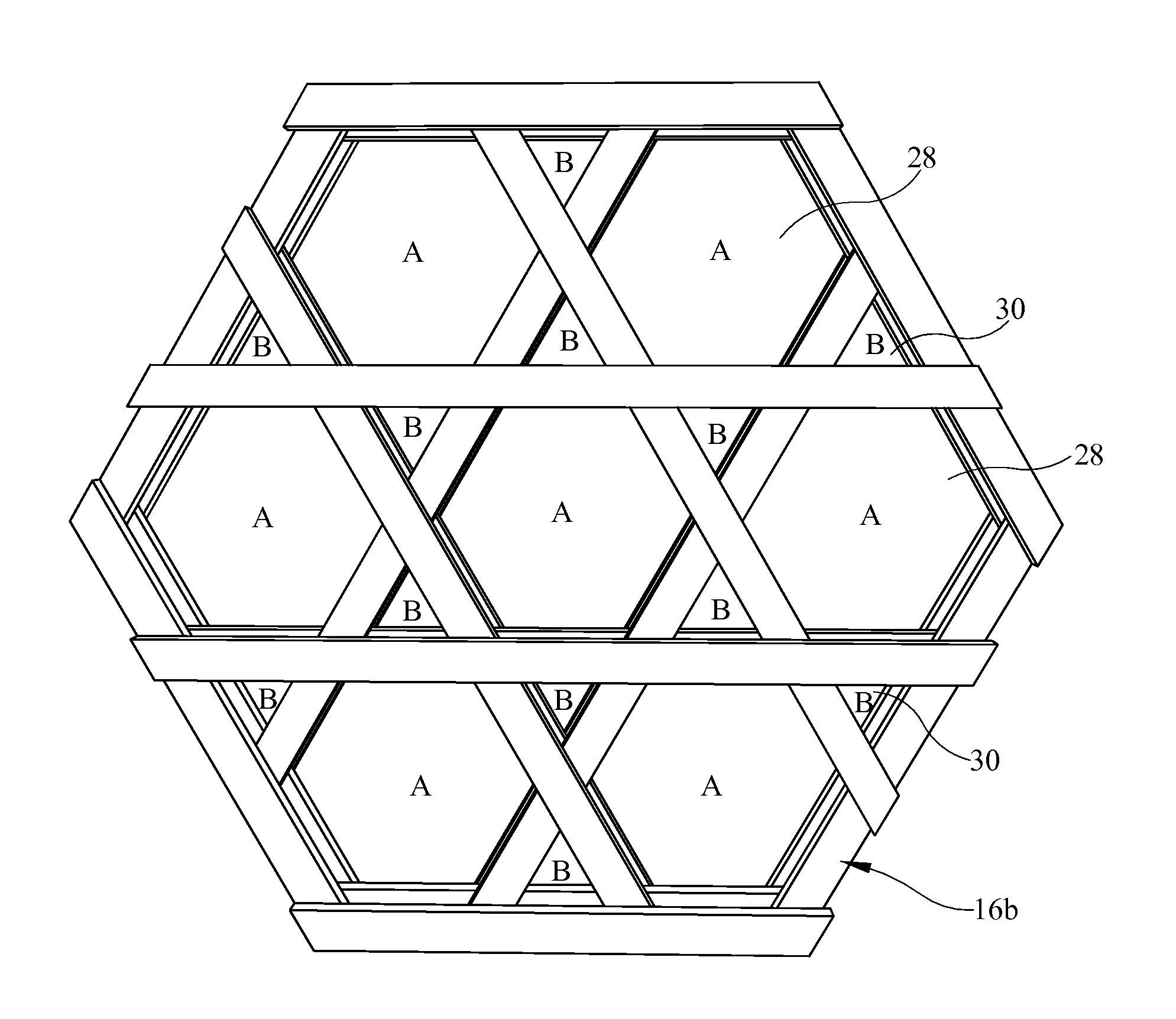
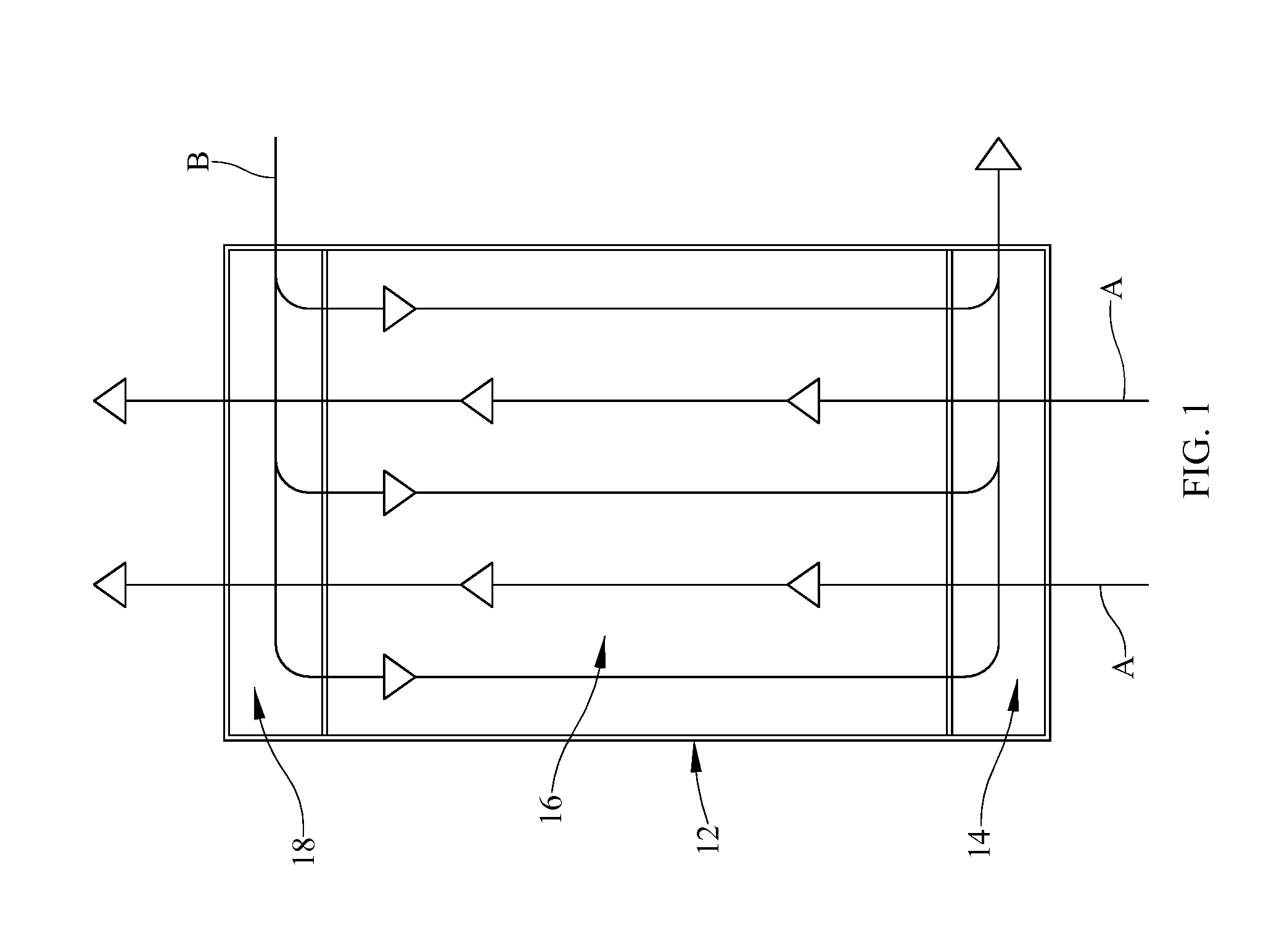
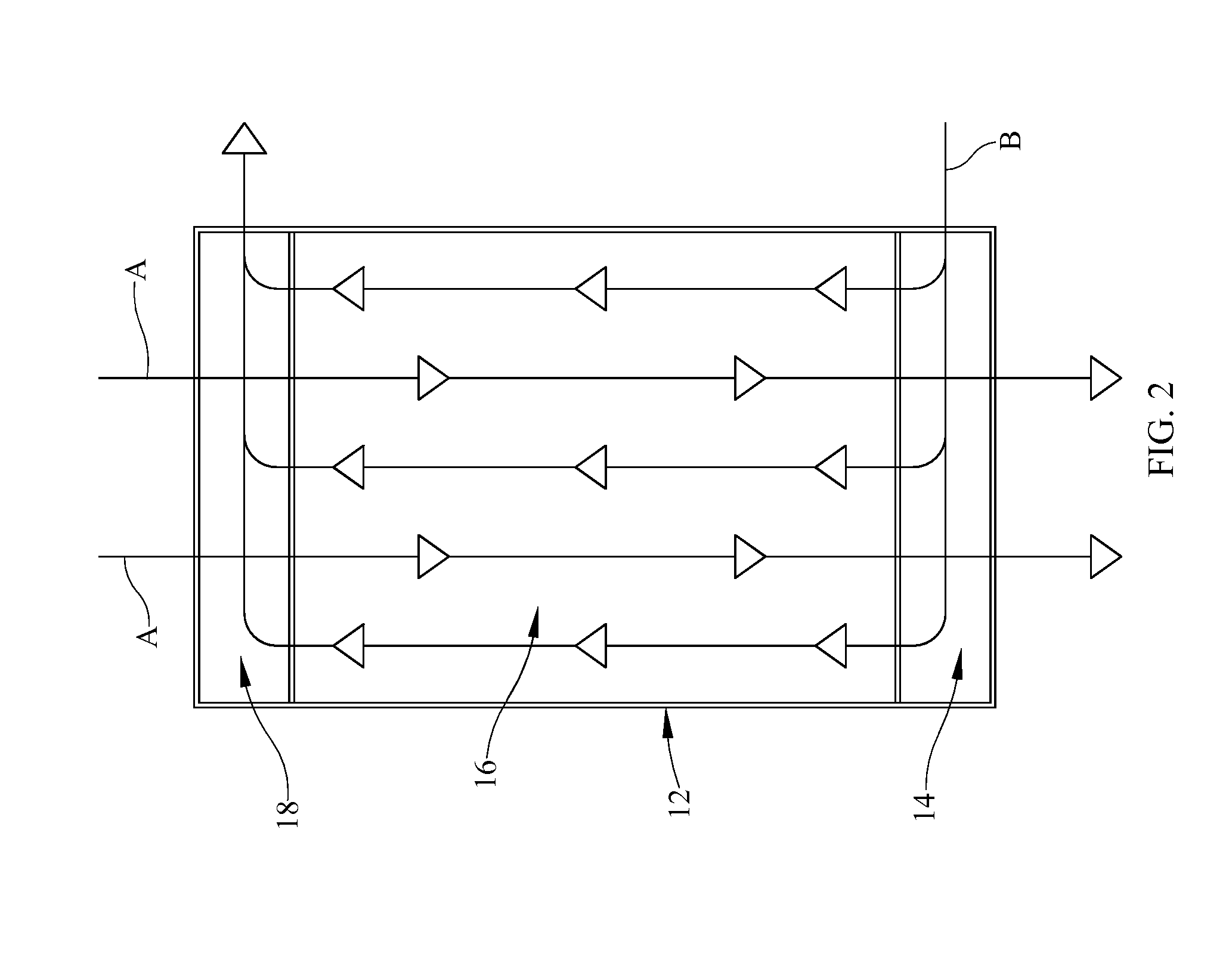
[0062]Referring now to the drawings, and specifically to FIGS. 1 and 2, it is seen that the fill material for direct contact heat / mass exchangers of the present invention, is used in a typical direct contact heat exchanger, which may or not be contoured—contoured heat exchangers are disclosed in patent application Ser. No. 14 / 242,635 filed on Apr. 1, 2014, and incorporated herein by reference in its entirety. Such direct contact heat exchangers may have fluid distributors / collectors of various forms depending on how much energy is required to move the fluids and the amount of energy available to perform the task. In a first possibility illustrated in FIG. 1, the heat exchanger 12 has a first fluid A that is a low-density, high-pumping-energy fluid and a second fluid B, which is a high-density low-pumping-energy fluid, with the first fluid

[0063]A entering the heat exchanger 12 at its bottom and flowing upwardly through a lower fluid distributor and collector 14, through the fill mate...


PUM

PropertyMeasurementUnit
sizesaaaaaaaaaa
contact anglesaaaaaaaaaa

Abstract

Fill material for a direct contact heat exchanger wherein the fill material has flow pathways bounded by an array of linear elements, namely a mesh. The invention intentionally uses surface tension and capillary action to anchor the fluid / fluid interface in a desired location. The heat exchanger is wick or collector in direct contact with the fill material (matrix) to extract fluid without formation of large droplets. The mesh is made from a neutrally wetting material.

Description

[0001]This application claims the benefit of U.S. provisional application No. 61 / 867,523 filed on Aug. 19, 2013 and U.S. provisional application No. 61 / 939,208 filed on Feb. 12, 2014, each application incorporated herein by reference in its entirety.BACKGROUND OF THE INVENTION[0002]1. Field of the Invention[0003]The present invention relates to neutrally-wetting fill material used in direct contact heat / mass exchangers.[0004]2. Background of the Prior Art[0005]A heat / mass exchanger is a device that moves heat and / or a dissolved substance (mass) from one fluid to another fluid. The ideal heat exchanger would move as much heat as is thermodynamically possible, causing the temperatures of the exiting fluids to be the reverse of the temperatures of the entering fluids; thus the exiting heat-sink fluid would be just as hot as the entering heat-source fluid and the exiting heat-source fluid would be just as cold as the entering heat-sink fluid. A practical heat exchanger cannot exchange a...

Claims


Application Information

Patent Timeline
Patent Type & Authority Applications(United States)
IPC IPC(8): B01J19/30F28D7/16
CPCF28D7/16B01J19/30B01J19/32B01J2219/32286B01J2219/32416F28F25/087B33Y80/00
Inventor BARTON, SEAN ANDERSON
Owner BARTON SEAN ANDERSON
Why Eureka
Try Eureka