Method of removing particulate debris with an interventional device

a technology of particulate debris and intervention device, which is applied in the field of intervention device to achieve the effect of improving overall extraction efficiency, good pressure recovery, and a large working area

Inactive Publication Date: 2009-02-24
SPRITE SOLUTIONS
View PDF8 Cites 50 Cited by
  • Summary
  • Abstract
  • Description
  • Claims
  • Application Information

AI Technical Summary

Benefits of technology

[0011]In contrast to the jets of the prior art, the present invention relies on a substantially annular sheet jet which is “bent” and flows around a “nubbin”. The asymmetries introduced by the nubbin results in flow which is deflected through an angle. This deflected jet is in the form of a vortex and it presents a large and energetic surface to entrain thrombus and other occlusive material. In operation the jet emerges from a generally annular gap or slot and attaches itself to a

Problems solved by technology

They range from simple aspiration de

Method used


Image

  • Method of removing particulate debris with an interventional device
  • Method of removing particulate debris with an interventional device
  • Method of removing particulate debris with an interventional device

Examples


Embodiment Construction

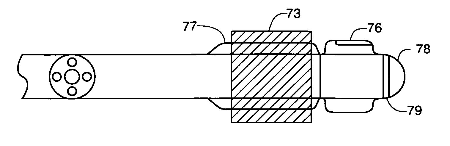
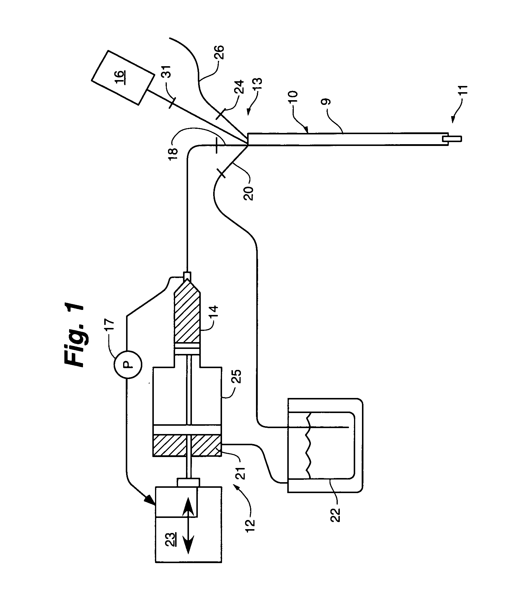
[0034]Turning to FIG. 1, the interventional device 10 is coupled to an injector 12. This interventional device 10 has a body 9 with a distal end 11 and a proximal end 13 and includes a high-pressure supply lumen 18. In this version there is a lower pressure discharge lumen 20 within the body 9. The high-pressure supply lumen 18 is located in the body as well and it is coupled to the injector 12 at the proximal end 13. In the figure the high pressure injector 12 supplies infusate which may be saline, thrombolytic fluid, contrast agent or the like, from a supply syringe 14. Throughout most of the drawings only the distal or “working” portion of the device is shown, as the details of length and construction are well known in this art.

[0035]The injector 12 may deliver infusate at a user selected delivery rate. In this mode the injector generates a corresponding pressure sufficient to induce the required flow. In an alternate mode of operation the injection pressure is specified and the ...


PUM


Abstract

The present invention relates to an interventional device for interacting with occlusive material. A wall attachment jet moves and removes particulate from lumens such as vessels.

Description

CROSS REFERENCE TO RELATED APPLICATIONS[0001]The present application is a Continuation of U.S. patent application Ser. No. 09 / 459,225 filed Dec. 10, 1999 now abandoned.[0002]The present application is a Continuation in Part of U.S. patent application Ser. No. 09 / 637,529 filed Aug. 11, 2000.[0003]Each application is incorporated in its entirety.FIELD OF THE INVENTION[0004]The invention relates generally to an interventional device, and more particularly to a device that utilizes the energy in a pressurized fluid to remove occlusive material from vessels or lumens in the body. The invention is disclosed in the context of the removal of blood thrombus.BACKGROUND OF THE INVENTION[0005]Catheters which are used to remove occlusive material from lumens within the body are well known. They range from simple aspiration devices to complex high energy devices[0006]Occlusive materials such as plaque, atheroma, and emboli vary in their mechanical properties and various energy sources have been p...

Claims


Application Information

Patent Timeline
IPC IPC(8): A61M31/00A61B17/22A61B18/24
CPCA61B17/22012A61B17/221A61B17/32037A61B17/320758A61B18/245
Inventor BECK, ROBERT C.MISCHE, HANS
Owner SPRITE SOLUTIONS
Why Eureka
Try Eureka