Mixer/heat exchanger

a heat exchanger and mixer technology, applied in indirect heat exchangers, lighting and heating apparatuses, transportation and packaging, etc., can solve the problems of insufficient achievement, long residence time, high pressure loss, etc., and achieve stable design, large heat-transfer surface area, and stable design

Inactive Publication Date: 2007-05-22
BAYER AG
View PDF14 Cites 45 Cited by
  • Summary
  • Abstract
  • Description
  • Claims
  • Application Information

AI Technical Summary

Benefits of technology

[0065]With the above mentioned invention, it is possible to form small, compact high-performance heat exchangers for low-viscosity and high-viscosity, liquid and gaseous substances. The apparatus have a very stable design, can be used with high pressure gradients on account of the stable design, have a large heat-transfer surface area and operate with little back-mixing. Particularly in the case of applications for controlling the temperature of viscous and highly viscous single-phase or multiphase substance systems, the advantages are particularly significant on account of short residence times.
[0066]The flow characteristics of very highly viscous substance systems imply a very high pressure loss, and consequently only low flow velocities are economically possible. The person skilled in the art speaks of creeping flows. In this case, the heat exchange between heat-transfer medium and product is particularly poor. In this application, in addition to the large heat-exchanging surface area, an intensive mixing operation is simultaneously required in order to achieve gentle and uniform heating of the product. Given a suitable arrangement of the finned tubes, the temperature of the product is controlled with a very short residence time and a narrow residence time spectrum, so that the mixer / heat exchanger according to the invention can be used to control the temperature in particular of temperature-sensitive substances.
[0067]In individual cases, the invention even makes is possible to dispense with a completely temperature-controlled housing, with the result that, inter alia, investment costs are reduced further.
[0068]On account of the high design flexibility of the mixer / heat exchangers according to the invention, by combining the tube spacings “a” and “h” with different fin regions, varying the number of the finned tubes next to one another, beneath one another or offset with respect to one another, and varying the tube spacings transversely to or in the main direction of flow of the product, it is possible to satisfy all process engineering and product-specific requirements.
[0069]In a particularly advantageous application, the apparatus can be operated with low temperature differences between inlet and outlet of the heat-transfer medium or the coolant, so that a high capacity heat transfer is possible during temperature control and very good utilization of the secondary energies is also possible.
[0070]The static mixer / heat exchanger of the present invention makes it possible to produce compact, pressure-resistant and inexpensive heat-transfer apparatus or tubular reactors with little back-mixing. The shape of mixer / heat exchanger units, which can be plugged into corresponding temperature-controlled housings, results in apparatus which are particularly easy to operate and allow simple cleaning.

Problems solved by technology

The rapid, uniform and gentle controlling of the temperature of viscous and highly viscous products, e.g. polymer melts, is only achieved to an insufficient extent using the known static mixer systems described below.
Temperature-control objectives of this type require long temperature-controlled mixing distances, on account of the low thermal conductivity of most organic substances, leading to a long residence time and a high pressure loss and therefore to damage to viscous substances (>1 mPa·s) with a laminar flow velocity, in particular those with a temperature-sensitive character.
An additional drawback of the long mixing distances is the high design-related investment costs involved with such systems.
Drawbacks such as the low mechanical stability and high pressure losses of known static mixers lead to the need for large cross sections of flow, which in turn make temperature control more difficult.
This results in limited metallic contact between the heated inner housing wall and the small outer cross-sectional areas of the metallic static mixers.
However, the static mixer which has been drawn or rolled in can only form an inadequate contact surface with the temperature-controlled housing wall.
Experience has shown that the contact surfaces are not formed completely, and consequently there are always gaps with respect to the inner housing wall.
Furthermore, these gaps represent “dead areas”, which contribute to the formation of specks, for example in polymer melts.
These specks (impurities) reduce the quality of the products sold (e.g. thermoplastics).
The mechanical preparations which have to be carried out on the parts to be soldered are complex and cost-intensive.
On account of the geometric structure of the static mixers, however, the contact surface with respect to the heated housing surface is very small, and consequently only a slightly higher temperature-control capacity with respect to the product flow is possible.
The increase in the size of the temperature-controlled surface area compared to the static mixers which are rolled in is not significantly higher, and consequently mixing distances with soldered static mixers cannot be shortened significantly.
On account of the limited overall size of soldering furnaces and on account of the distortion caused to the tubes during soldering, the soldering process is only possible for a short length of tube (generally <2 m).
Moreover, the solder used means that additional corrosion problems often occur and have to be taken into account during use of mixers of this type, in order to ensure that, for example, the purity and quality of a product are not adversely affected by impurities resulting from corrosion.
These designs are not pressure-stable and do not have any mixing properties for viscous substances in the laminar flow region.
Therefore, tube systems of this type are not suitable for controlling the temperature of viscous and highly viscous liquids.
The solders used (e.g. zinc, tin) cannot be used in chemical processes with high corrosion specifications, and furthermore the mechanical strength of solders of this type is very low, in particular in the event of high thermal loads.
Since flow-facing round profiles have a low mixing action, a homogeneous temperature distribution in a high-viscosity product flow cannot be achieved to a sufficient extent over a short distance.
Particularly when the temperature of viscous substances, which have heat-insulating properties, is being controlled, the large heating surface area cannot be utilized effectively, since the internals do not have a good mixing action.
The bent plug-in tube bundles are susceptible to large pressure gradients.
The inner heat-transfer internals of the apparatus tend to be deformed in the process, and further control of the temperature of the product is then no longer possible, on account of the absence of diversion of the product.
The undesired stretching of the tube bundle is irreparable and may lead to the plant having to be shut down, with high downtime costs.
On account of the ideally elongated length of the individual tube and the small cross section of flow, the temperature-controllable meandering tube bundle has a high pressure loss and a long residence time on the temperature-control side.
The combination of the two, i.e. pressure loss and residence time of for example the temperature-control medium in the meandering turns, leads to considerable differences between the inlet temperature and the outlet temperature and reduces the mean temperature difference between the product and the heat transfer media, which is important for heat transfer, significantly.
Consequently, the heat-transfer performance of meandering tube bundles of this type is low.
In practice, a plurality of tube bundles are often connected in series, and this in turn increases the investment costs, the pressure loss, and the residence time of the substance whose temperature is to be controlled (i.e., the product) and also increases the outlay on assembly.

Method used


Image

  • Mixer/heat exchanger
  • Mixer/heat exchanger
  • Mixer/heat exchanger

Examples


example 1

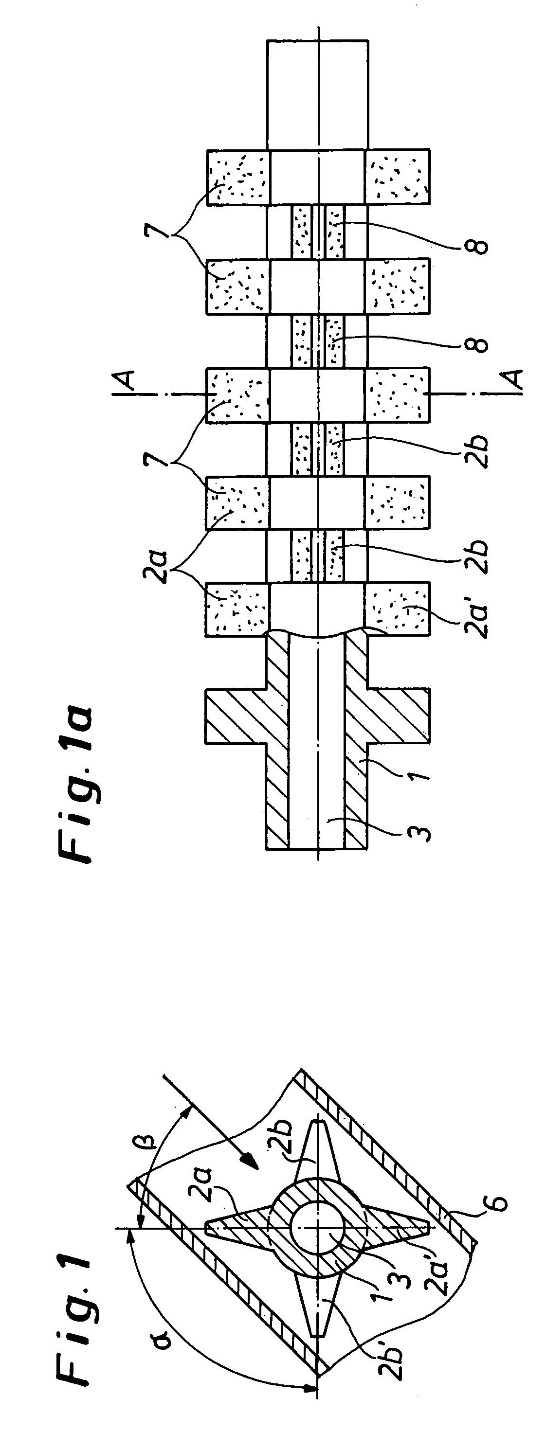
[0092]FIG. 1 shows a single-piece tube 1 in a housing 6 through which product flows, which tube, on the outer circumference, has a finned region and two radial mixing fins 2a, 2a′, which are at an angle β+45 or −135° with respect to the main direction of flow (arrow) in a front finned region, illustrated in section, and a rear finned region with two further fins 2b, 2b′. The width of the finned region is in this case selected in such a way that two fin layers each having two fins 2a, 2a′ and 2b, 2b′ are arranged alternately along the tube axis, radially offset with respect to one another, in the housing 6, and adjoin one another without any gaps in terms of their axial extent (cf. FIG. 1a).

[0093]The shape or configuration of the fins and the surface condition of the fins may differ. The surface of the fins and of the tube may, for example, be structured by elevated bosses, studs or flutes or grooves, in order to increase the heat-transfer surface area and to produce additional flow ...

example 2

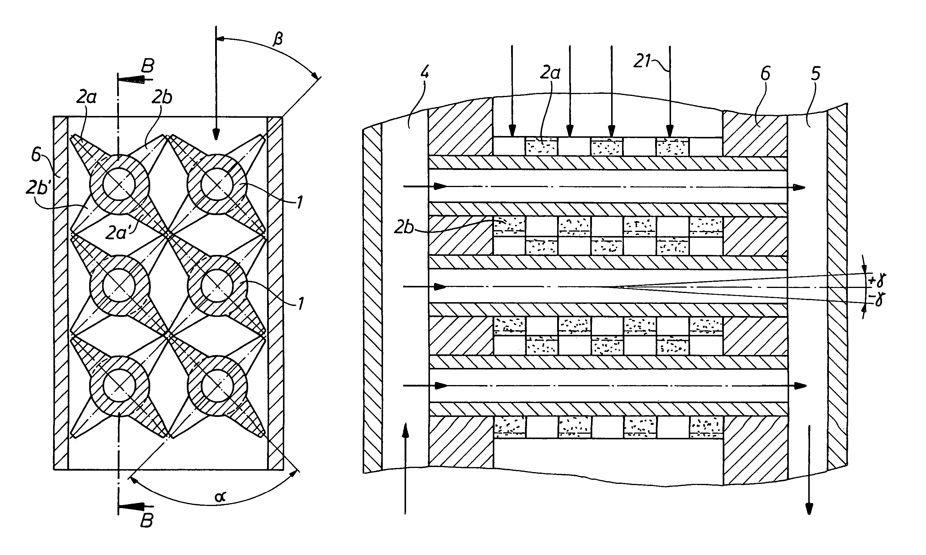
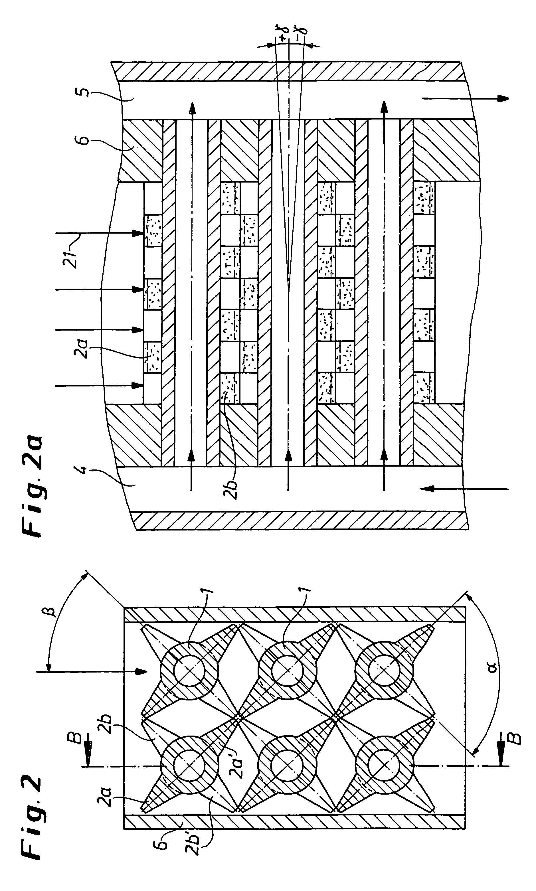
[0103]A further mixer / heat exchanger is represented in longitudinal section in FIG. 2. Six tubes 1 have two parallel layers of fins 2a and 2b, each having two radially offset fins 2a, 2a′ on the outer circumference of the tubes. One end of the tubes 1 opens into a heat-transfer medium supply chamber 4, and the other to a heat-transfer medium discharge chamber 5 (FIG. 2a). The tubes 1 are welded to the supply chamber 4 and the discharge chamber 5. The tubes 1 are at an angle γ of approximately 5° transversely with respect to the main direction of flow 21 of the product. The tubes 1 with the fins are positioned in such a way that the fins are positioned at an angle β of 45° with respect to the incoming product flow 21. The fins 2a are at an angle α of 90° with respect to the offset fins 2b.

[0104]The supply chamber 4 and discharge chamber 5 of the temperature-control agent comprise a pocket or half-tube (not shown) welded to the housing 6.

example 3

[0105]FIG. 10 shows a mixer / heat exchanger unit, having a rectangular housing 6 and three finned tubes 1, 1′, 1″. In terms of their structural shape, the fins 12a, 12b correspond to the types shown in FIG. 3, and they are arranged in alternating layers over the length of the tubes 1, 1′, 1″.

[0106]In the cross section shown in FIG. 11 on line IV—IV from FIG. 10, it can be seen that two chambers 4, 5, which are connected to a feedline 16 and a discharge line 17 for a liquid heat-transfer medium (cf. FIG. 12), are formed by an outer casing 15. As shown in FIG. 11, in operation the heat-transfer medium 18 flows through the tubes 1, 1′, 1″. At their one end the tubes 1, 1′, 1″ have a constriction 3′ in the passage 3.

[0107]The mixer / heat exchanger (cf. sectional illustration in FIG. 12) has a rectangular product-flow region formed by the housing 6. The further housing 15, which surrounds the housing 6 and is divided by partition fins, forms the chambers 4, 5 for the heat-transfer medium 1...


PUM

PropertyMeasurementUnit
angleaaaaaaaaaa
angleaaaaaaaaaa
en angleaaaaaaaaaa

Abstract

A combination static mixer and heat exchanger having heat exchanger tubes (1) which are provided over their circumference with fins (2a, 2b) which have a static mixing effect.

Description

[0001]The invention relates to a combination of static mixer and heat exchanger for the process engineering treatment of thermally sensitive viscous media, comprising a plurality of tubes which are arranged in parallel next to, above or offset with respect to one another, are positioned transversely, at an angle, preferably of 90°, with respect to the direction of flow of the product, in a housing and to which media flow. On their external diameter, the tubes have raised, radially arranged fins or curved fins which are arranged axially offset with respect to the tube axis and are offset with respect to one another on the tube axis. The raised fins are arranged in such a way that, particularly in the case of viscous and highly viscous substances and substance mixtures, a good mixing action is produced and, at the same time, the significantly increased tube external surface area (i.e., as increased by the fins) for the first time allows rapid temperature control which is gentle on the...

Claims


Application Information

Patent Timeline
Patent Type & Authority Patents(United States)
IPC IPC(8): B01F15/06B01F23/47F28D7/16F28D7/00F28F9/22F28F13/06
CPCB01F3/10B01F5/0618B01F15/066F28D7/0058F28F9/22F28F13/06B01F2215/0422B01F2215/0495B01F23/47B01F25/4316B01F35/93
Inventor KOHLGRUBER, KLEMENSJAHN, PETER
Owner BAYER AG
Why Eureka
Try Eureka