

Extension device
a technology of extension device and stent, which is applied in the field of extension device, can solve problems such as difficult control, and achieve the effects of convenient pivoted, endangering the sterility of the operation location, and convenient coupling and decoupling
- Summary
- Abstract
- Description
- Claims
- Application Information
AI Technical Summary
Benefits of technology
Problems solved by technology
Method used
Image

Examples
Embodiment Construction
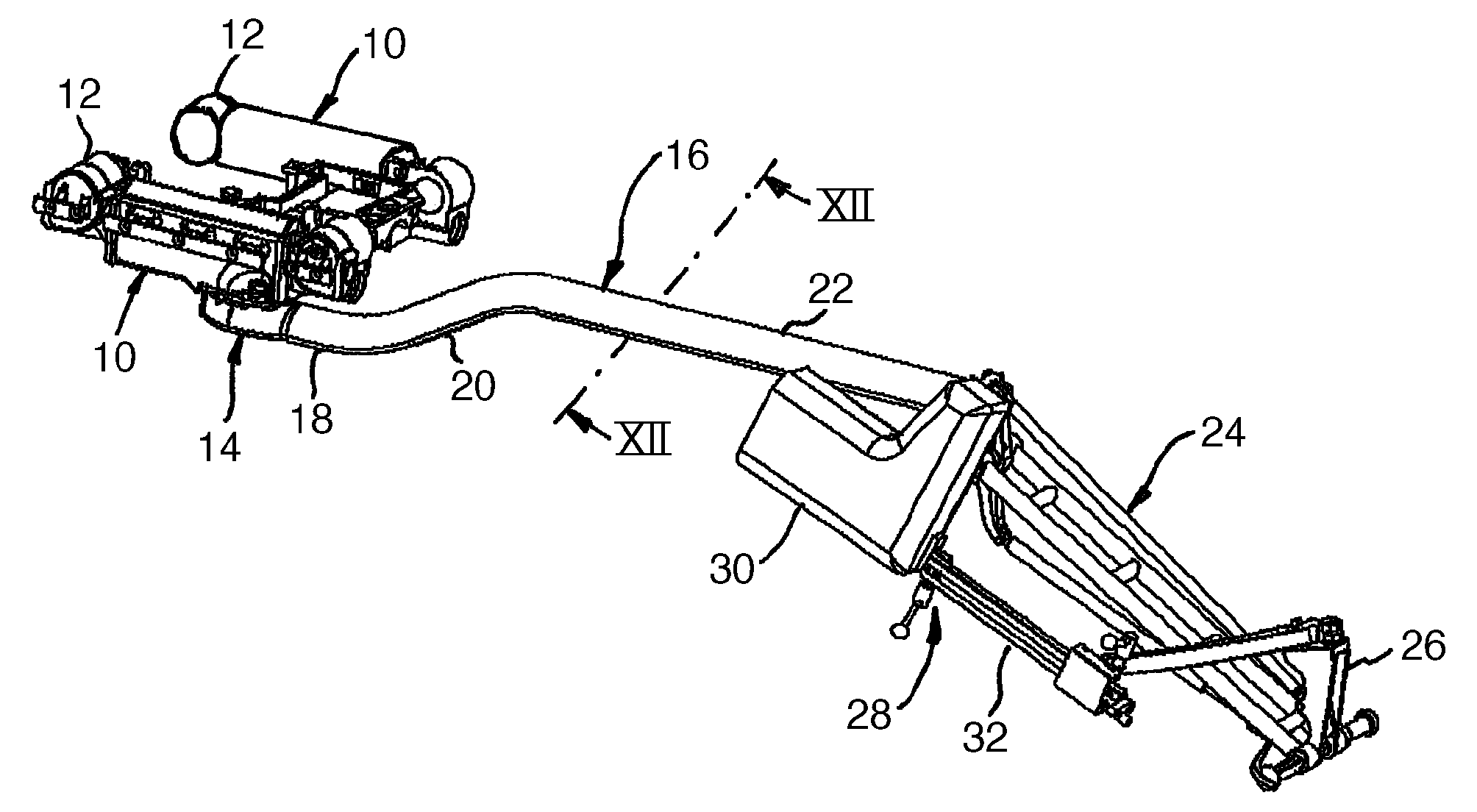
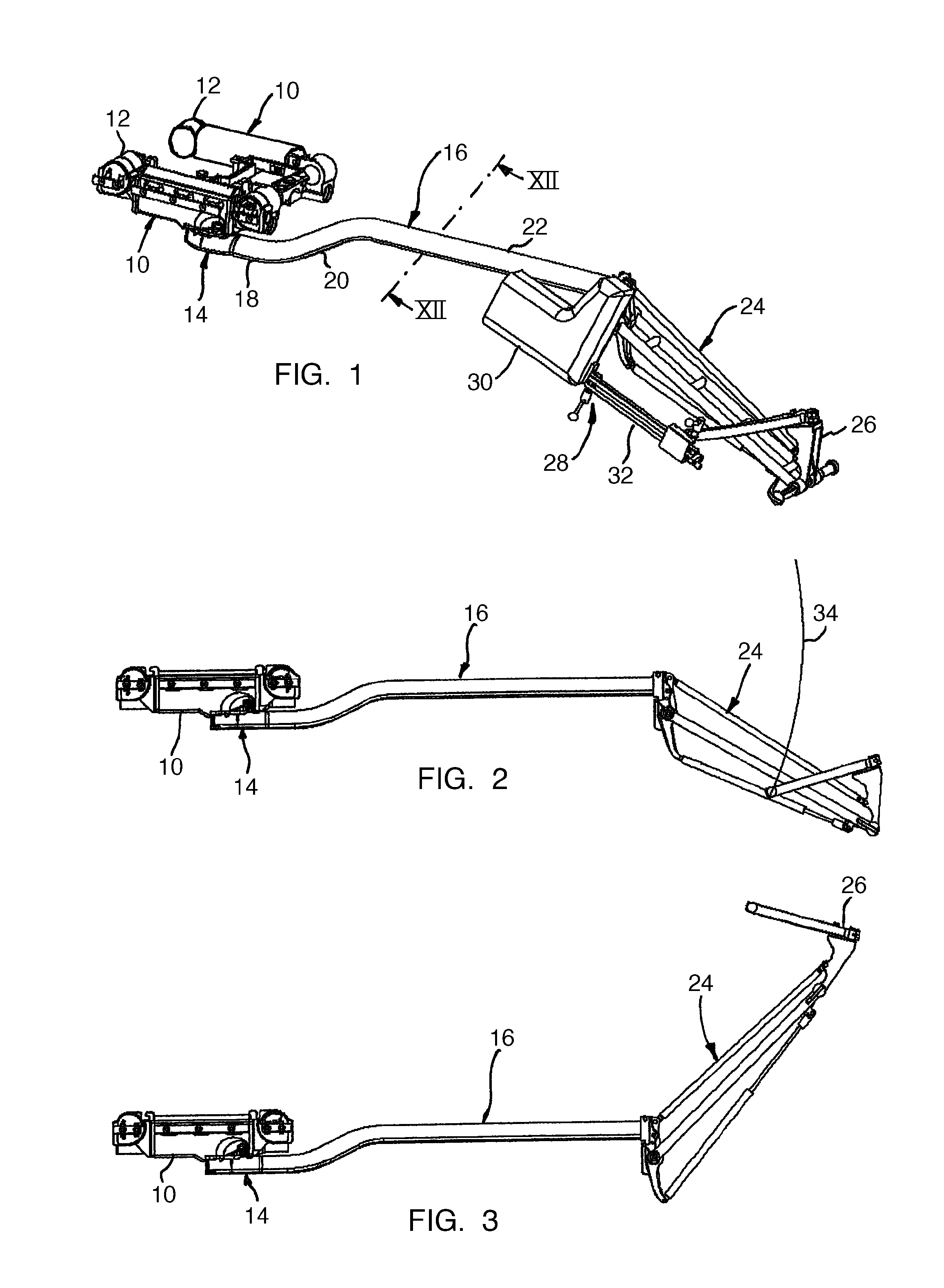
[0026]The extension device shown in FIG. 1 comprises a schematically shown part of a patient support surface with two support surface beams 10 that are parallel to one another and that each have connection elements 12 on their longitudinal ends for attaching other support surface parts. The support surface beams 10 carry a pelvic plate (not shown) for supporting a patient. An extension beam designated in general with 16 is coupled at an interface 14 to one of the support surface beams 10. The extension beam is formed by a bent tube that comprises a first straight section 18 in the vicinity of the support surface, a bent transitional section 20, and a second section 22 parallel to the first section 18. The tube is manufactured from composite carbon fiber material and has an oval cross section shown in FIG. 12.
[0027]The extension beam is connected at its end remote from the support surface section to a linkage 24 with four articulations that carries a holder 26 for a feed rod unit 28....
PUM
 Abstract
Description
Claims
Application Information