
Seat load sensing apparatus

Inactive Publication Date: 2006-08-31
TRW AUTOMOTIVE US LLC
View PDF30 Cites 1 Cited by
  • Summary
  • Abstract
  • Description
  • Claims
  • Application Information

AI Technical Summary

Problems solved by technology

This construction exposes the sensor to large dynamic loads over short periods of time, such as during a collision to the vehicle.
Thus, the sensor may not produce a reliable vertical load output signal subsequent to such a dynamic loading event.

Method used


Image

  • Seat load sensing apparatus
  • Seat load sensing apparatus
  • Seat load sensing apparatus

Examples


Embodiment Construction

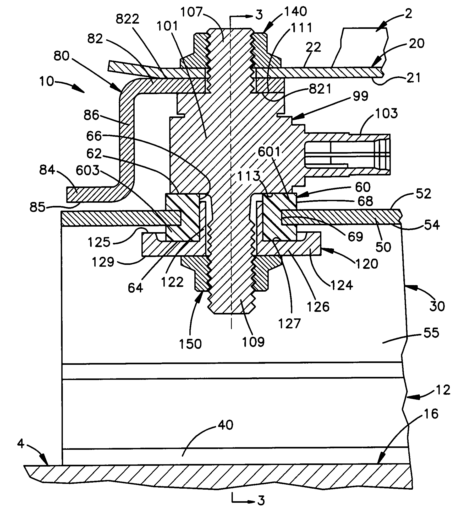
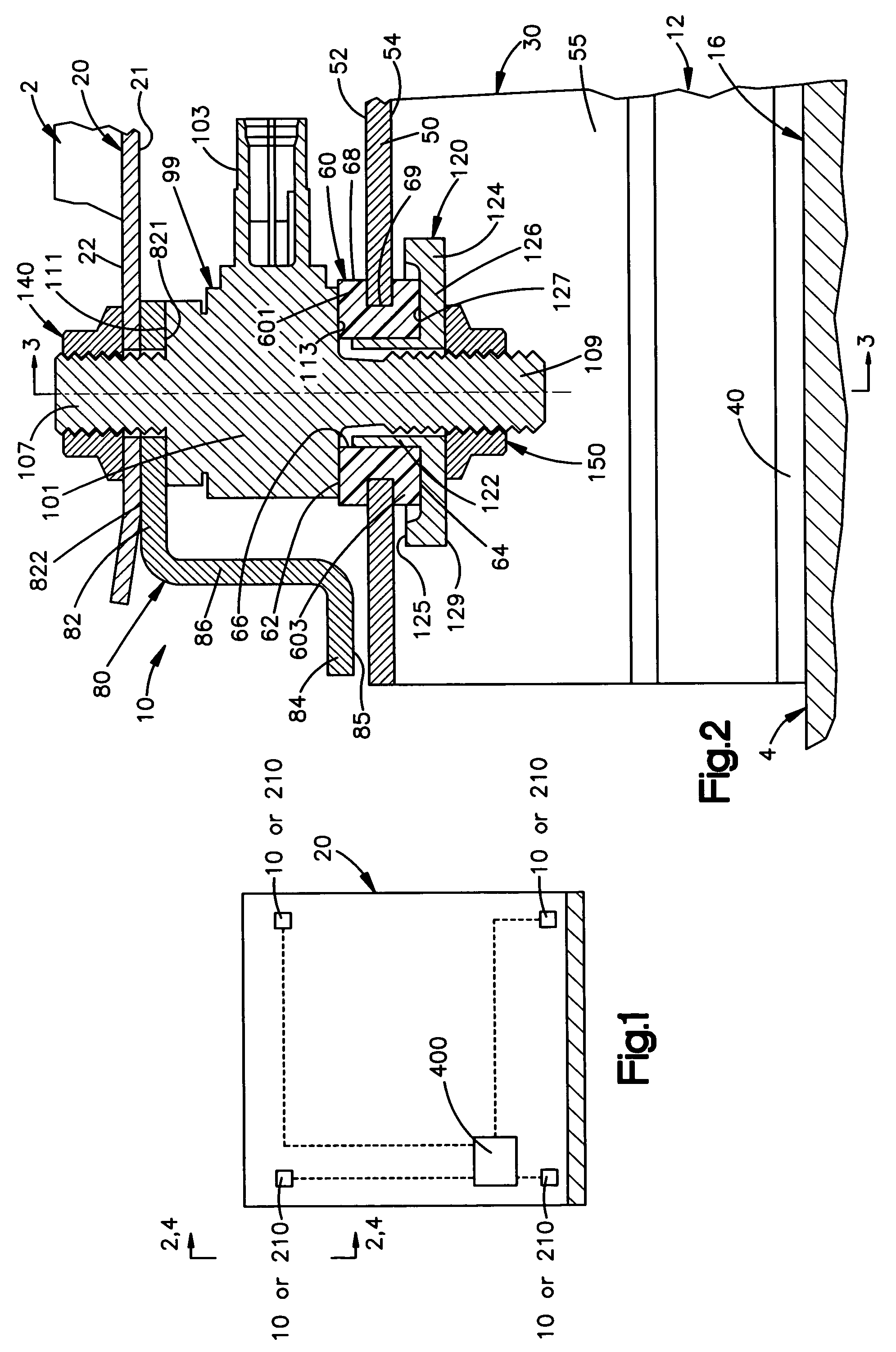
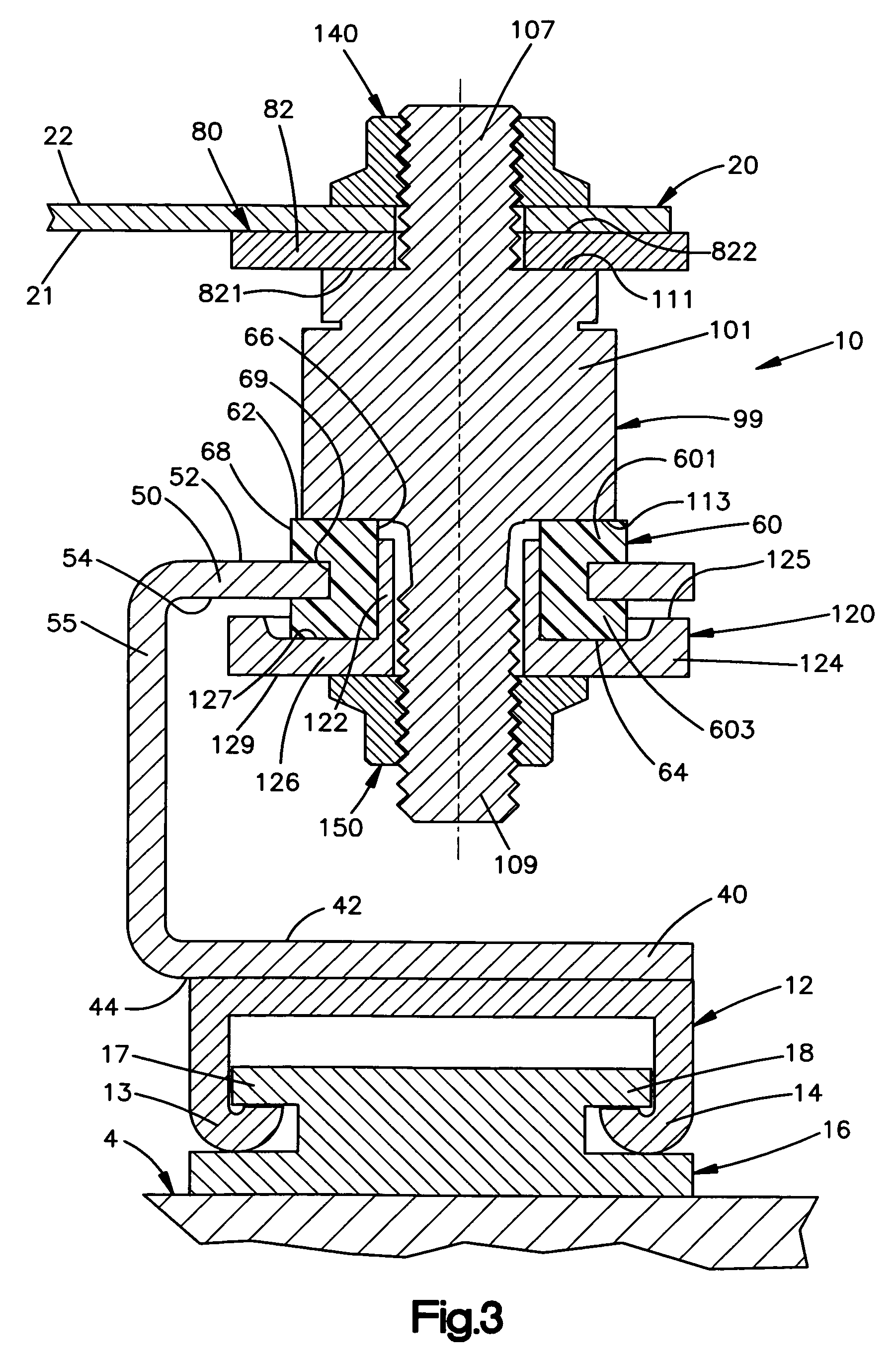
[0013] According to an aspect of the present invention, as shown in FIGS. 1-3, a vehicle occupant load sensing apparatus 10 is used in a vehicle having a seat 2 for the vehicle occupant. A vehicle floor pan 4 supports the vehicle seat 2. The apparatus 10 includes a vehicle seat frame 20 for supporting the vehicle seat 2, a sensor 99 for sensing a load placed on the vehicle seat, a resilient member 60 for absorbing dynamic loads imparted to the sensor by the vehicle seat, a bracket 30 for transmitting the load from the vehicle seat to the vehicle floor pan, an upper track 12 for supporting the bracket, and a lower track 16 for adjustably supporting the upper track.

[0014] The vehicle seat frame 20 supports a weight load of the vehicle occupant in the vehicle seat 2. During a vehicle collision, the seat frame 20 may also sustain upward and lateral loads created by the vehicle collision. The load of the vehicle occupant in the vehicle seat 2 is transmitted through the sensor 99, the br...


PUM


Abstract

An apparatus (10) is used in a vehicle having a vehicle seat (2) for a vehicle occupant and a vehicle floor pan (4) for supporting the vehicle seat (2). The apparatus (10) includes a vehicle seat frame (20), a sensor (99), and a member (60). The vehicle seat frame (20) supports a load of the vehicle occupant in the vehicle seat (2). The vehicle seat frame (20) is movable vertically upon application of a vertical load to the vehicle seat frame (20). The sensor (99) transfers the load of the vehicle occupant in the vehicle seat (2) from the vehicle seat frame (20) to the vehicle floor pan (4). The sensor (99) detects a part of the load of the vehicle occupant and provides an output signal indicative of the amount of the part of the load transferred. The member (60) damps force transferred by the vehicle seat (2) and the vehicle seat frame (20) to the vehicle floor pan (4). The member (60) is interposed between the vehicle floor pan (4) and the sensor (99).

Description

TECHNICAL FIELD [0001] The present invention relates to an apparatus for sensing a load, and more particularly, to an apparatus for sensing the load imparted to a vehicle seat by a vehicle occupant. BACKGROUND OF THE INVENTION [0002] A conventional vehicle occupant load sensing apparatus includes a load sensor placed between a corner of a vehicle seat frame and a support mount for the seat. The sensor is directly within the vertical load path of the occupant's weight and responds to the vertical loads imparted to the seat by the occupant of the seat. In addition, the sensor may respond to torque loads between the seat and the support mount. Since the seat frame and the support mount must withstand large torque loads (i.e., tilting of the seat frame during crash conditions), typically the sensor also must be constructed to withstand large torque loads. [0003] This construction exposes the sensor to large dynamic loads over short periods of time, such as during a collision to the vehi...

Claims


Application Information

Patent Timeline
IPC IPC(8): A47C31/00A47C7/62
CPCA47C31/00
Inventor WOLFE, GEORGE B.
Owner TRW AUTOMOTIVE US LLC
Learn More