Quantitative and variable hydraulic system of loading machine

A hydraulic system and loader technology, applied in the field of loader fixed variable hydraulic system, can solve the problems of high cost and high energy consumption of variable hydraulic system, achieve low installed cooling power, long oil life, and reduce the loss of opening and middle position. Effect

Active Publication Date: 2014-09-10
GUANGXI LIUGONG MASCH CO LTD
View PDF4 Cites 28 Cited by
  • Summary
  • Abstract
  • Description
  • Claims
  • Application Information

AI Technical Summary

Problems solved by technology

[0004] The object of the present invention is to provide a loader constant variable hydraulic system with low cost and energy saving in view of the shortco

Method used


Image

  • Quantitative and variable hydraulic system of loading machine
  • Quantitative and variable hydraulic system of loading machine

Examples


Embodiment Construction

[0017] The specific implementation will be described below in conjunction with the accompanying drawings.

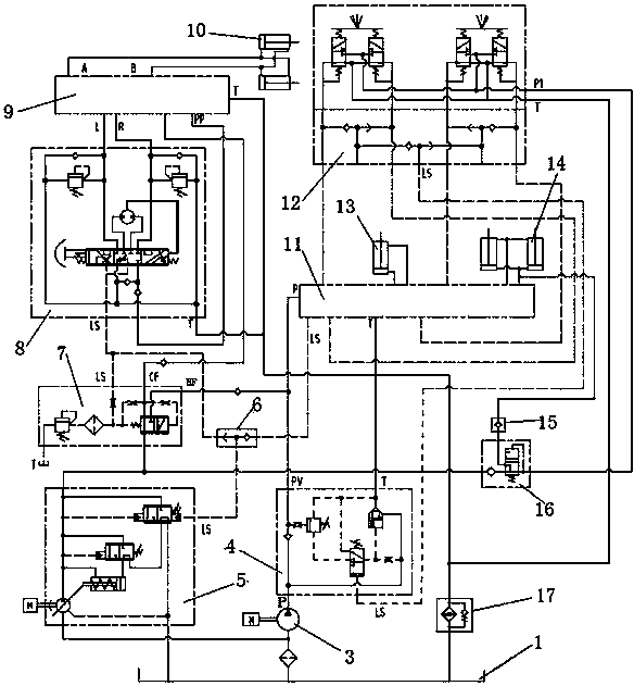
[0018] Such as figure 1 As shown, the loader constant variable hydraulic system in this embodiment includes a load sensitive variable pump 5, a load sensitive steering gear 8, a load sensitive flow amplifying valve 9, a steering cylinder 10, a quantitative pump 3, a load sensitive distribution valve 11, a pilot Valve 12, working oil cylinder, oil tank 1, unloading valve 4, priority valve 7, shuttle valve 6, second check valve 15, pilot oil source valve 16, working oil cylinder refers to bucket oil cylinder 13 and boom oil cylinder 14. The load sensing steering gear 8 is connected with the load-sensing flow amplifying valve 9 and controls the steering cylinder 10 connected with the load-sensing flow amplifying valve 9 through the load-sensing flow amplifying valve 9, thereby constituting the steering hydraulic system. The pilot valve 12 is connected with the load-sensing...


PUM


Abstract

The invention relates to a quantitative and variable hydraulic system of a loading machine. The shortcomings that a quantitative hydraulic system in an existing loading machine hydraulic system is high in energy consumption, and a variable hydraulic system in the existing loading machine hydraulic system is high in cost are overcome. The quantitative and variable hydraulic system is characterized in that a load sensing steering gear and a load sensitive flow amplification valve are connected to control a steering oil cylinder; a pilot valve and a load sensitive distribution valve are connected to control a working oil cylinder; an oil outlet of a load sensitive variable pump passes through a pressure-gradient control valve to be respectively communicated with an opening P of the load sensitive flow amplification valve and an opening P of the load sensitive distribution valve, a metering pump passes through an unloading valve to be communicated with the opening P of the load sensitive distribution valve, an opening LS of the unloading valve obtains a pilot oil pressure signal from the pilot valve, and an opening LS of the load sensing steering gear and an opening LS of the pressure-gradient control valve are communicated to provide a loading pressure signal for the load sensitive variable pump through a shuttle valve with the load sensitive distribution valve. By means of the quantitative and variable hydraulic system, overflowing losses, medium-position opening losses and high-pressure unloading losses are avoided, the energy consumption and the cooling power are low, and the oil liquid service life is long.

Description

technical field [0001] The invention relates to a loader hydraulic system, in particular to a loader constant displacement hydraulic system. Background technique [0002] Most of the existing loader hydraulic systems in China are quantitative hydraulic systems. Its hydraulic system consists of quantitative pump, steering gear, flow amplification valve (priority valve), steering cylinder, distribution valve, boom cylinder, bucket cylinder and other components. In the existing loader quantitative hydraulic system, the energy loss of the quantitative pump is ignored. Since the pump displacement is a fixed value, the system flow rate is only related to the engine speed; when turning alone, except for the flow required for steering, the excess flow returns to the fuel tank through the middle position of the distribution valve with a certain back pressure, resulting in energy loss; during transportation In the working condition, the steering cylinder, the boom cylinder and the b...

Claims


Application Information

Patent Timeline
IPC IPC(8): E02F9/22
Inventor 梁振国王允黄胜
Owner GUANGXI LIUGONG MASCH CO LTD
Why Eureka
Try Eureka