Apparatus for displaying drawings

a technology for displaying drawings and displays, applied in the direction of identification means, display means, instruments, etc., can solve the problems of not being able to adapt well to the type of drawings involved or the environment, requiring too much power, and being too large and heavy for someone moving around a construction site,

Inactive Publication Date: 2006-09-07
E INK CORPORATION
View PDF42 Cites 77 Cited by
  • Summary
  • Abstract
  • Description
  • Claims
  • Application Information

AI Technical Summary

Problems solved by technology

Although electronic storage of the necessary drawings would appear to be the solution, the display devices conventionally used with electronic storage are not well adapted for either the type of drawings involved or the environment in which they have to be used.
Computer monitors based on cathode ray tubes are, of course, too large and heavy, and require too much power, to be useful to someone moving around a construction site.
Liquid crystal displays of the type used in portable computers are sufficiently light in weight and have sufficiently low power consumption for such purposes, but are fragile and difficult to read in sunlight.
Furthermore, the maximum size of such displays is limited to about 15 inches diagonal, whereas construction drawings need to be much larger (typically about 24 by 36 inches) in order to show to scale details of a large building or device, and it is difficult to work with such drawings without seeing the whole drawing at once.
Finally, construction sites present severe environmental hazards to portable computers, which may be damaged by rain, mud, blowing dust or excessive heat or cold.
Similar problems are encountered by others needing access to large numbers of complex drawings, for example aircraft maintenance technicians.

Method used


Image

  • Apparatus for displaying drawings
  • Apparatus for displaying drawings
  • Apparatus for displaying drawings

Examples


Embodiment Construction

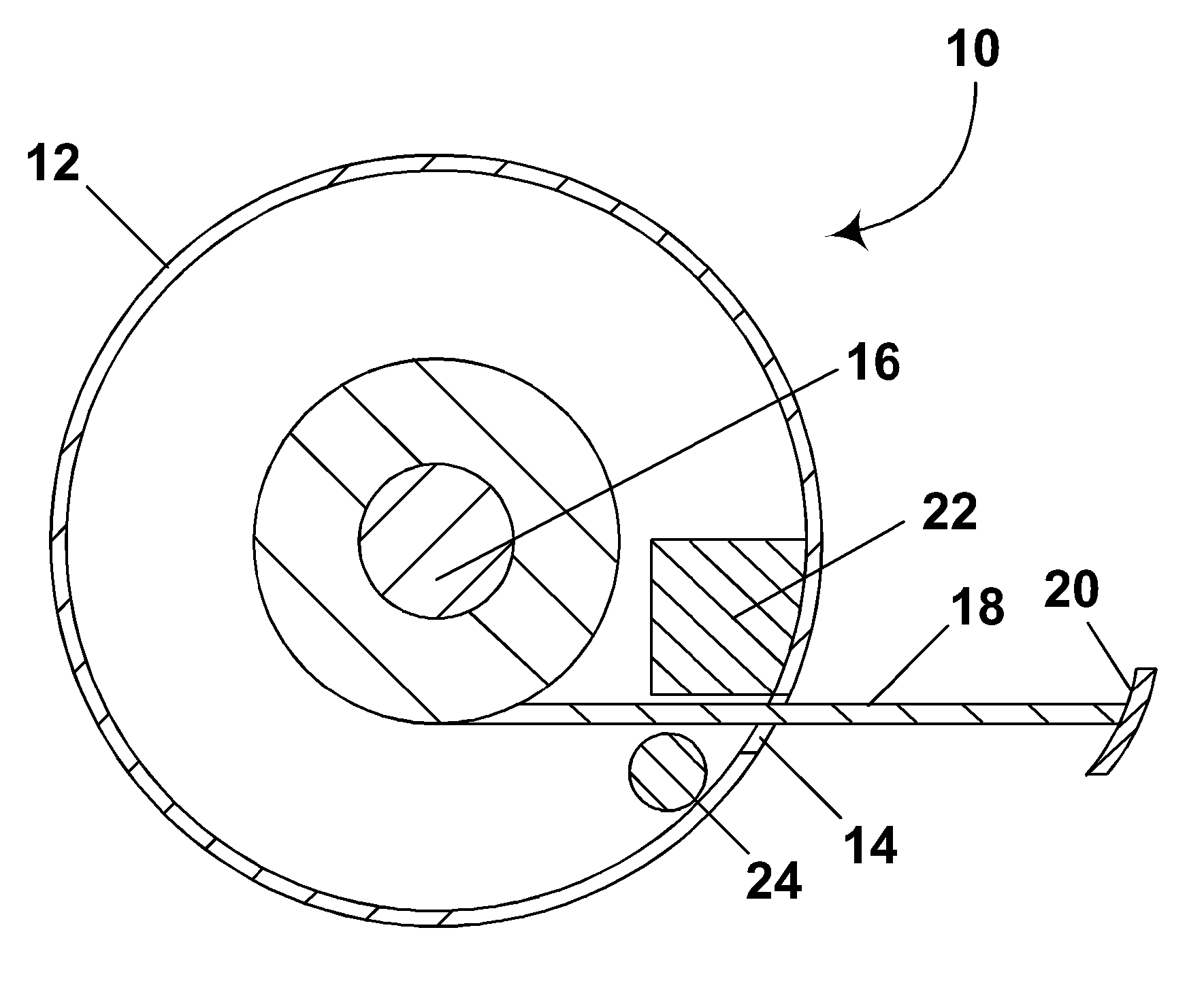
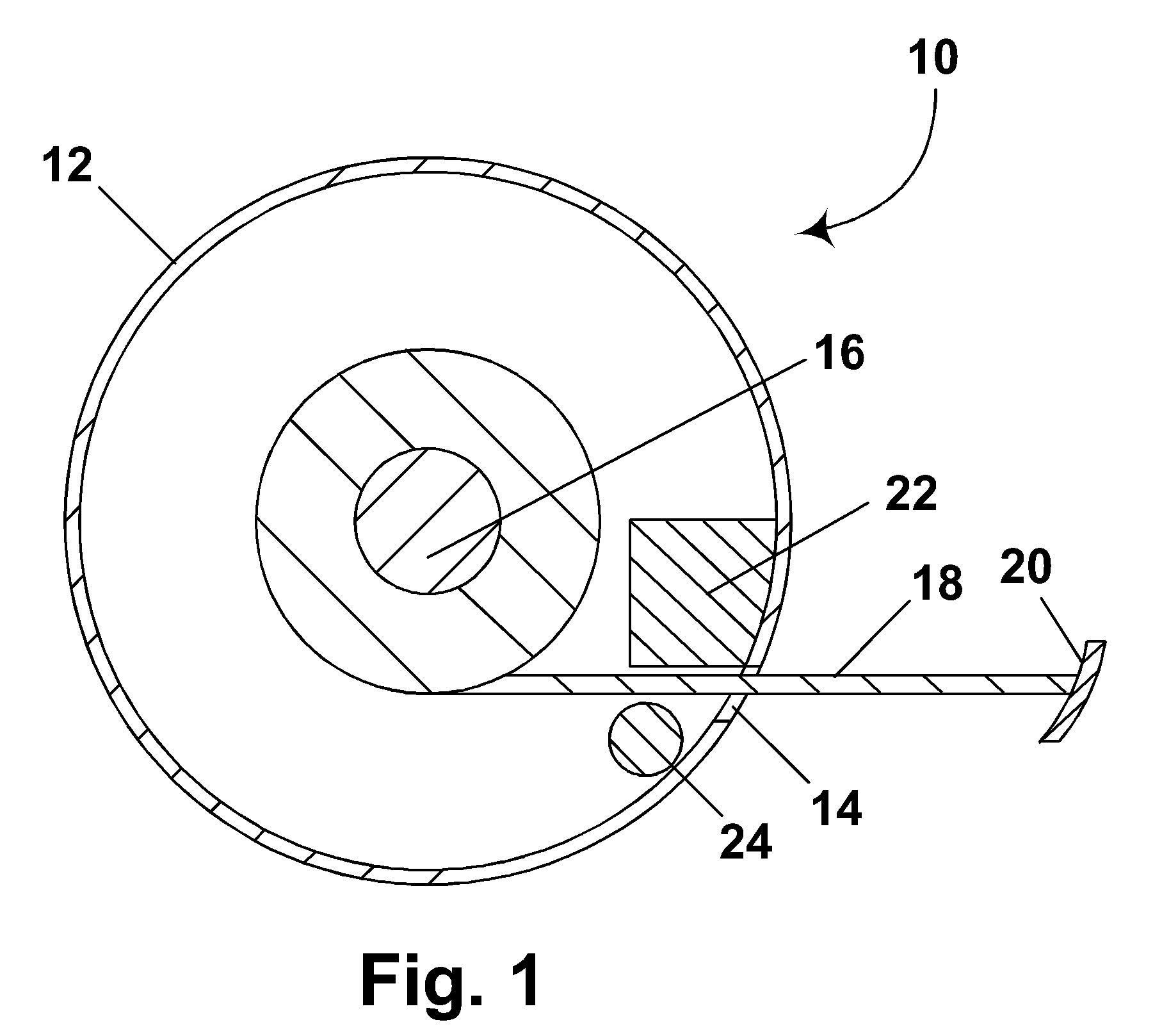
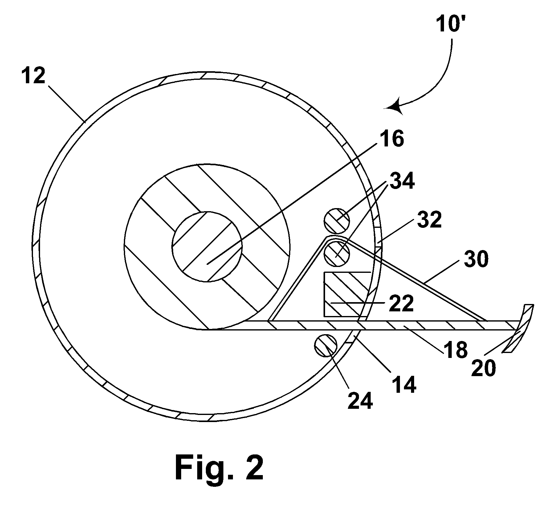
[0021] As already mentioned, in a first aspect this invention provides a “tube” apparatus for displaying a drawing, this apparatus comprising a housing having an aperture therein, and a drawing sheet movable through the aperture between an open and a closed position. An electro-optic medium having first and second display states differing in at least one optical characteristic is provided on the sheet, and the apparatus comprises writing means for writing on the electro-optic medium as the sheet is being moved from its closed to its open position.

[0022] This tube apparatus of the invention may have a rotatable spindle disposed within the housing, the drawing sheet, when in its closed position, being wound around the spindle, the drawing sheet being moved from its closed to its open position by being unwound from the spindle. In a preferred form of such a tube apparatus, the housing is substantially cylindrical, the spindle has an axis of rotation substantially parallel to the axis ...


PUM

PropertyMeasurementUnit
sizeaaaaaaaaaa
sizeaaaaaaaaaa
electric fieldaaaaaaaaaa

Abstract

A first apparatus for displaying drawings comprises a housing having an aperture, a drawing sheet comprising electro-optic material movable through the aperture between closed and open positions, and a writing device for writing on the sheet as it moved between its closed and open positions. A second apparatus comprises a display member having a viewing surface, support means for supporting this display member above a floor, an electro-optic medium disposed on the display member, and a movable writing head for writing on the electro-optic medium. Another display comprises an optic medium with two display states visible through a viewing surface. A touch screen is disposed on the opposed side of the optic medium from the viewing surface, and the optic medium is deformable such that pressure applied to the viewing surface will be transmitted to the touch screen.

Description

CROSS REFERENCE TO RELATED APPLICATIONS [0001] This application is a continuation of application Ser. No. 10 / 063,023, filed Mar. 13, 2002 (Publication No. 2002 / 0130832), which claims priority from Provisional Application Ser. No. 60 / 275,291, filed Mar. 13, 2001.BACKGROUND OF INVENTION [0002] The present invention relates apparatus for displaying drawings. More specifically, this invention relates to an apparatus for displaying drawings which makes use of a rewritable medium, preferably an electrophoretic medium. [0003] The present invention also relates to displays incorporating touch screens. [0004] The term drawings is used herein to cover, inter alia, construction drawings, blueprints, architectural drawings, maps, plans, and similar types of technical drawings which may be required, for example, for the assembly, repair and maintenance of machinery. [0005] Electro-optic displays comprise a layer of electro-optic material, a term which is used herein in its conventional meaning i...

Claims


Application Information

Patent Timeline
Patent Type & Authority Applications(United States)
IPC IPC(8): G09G3/34G02F1/15G02F1/167G02F1/17G06F3/041G09F7/10G09F9/00G09F9/30G09F9/37
CPCG09F7/10G09F9/372
Inventor BAUCOM, ALLAN SCOTTKNAIAN, ARA N.LINDEN, HEATHER A.O'MALLEY, TIMOTHY J.WILCOX, RUSSELL J.
Owner E INK CORPORATION
Why Eureka
Try Eureka