
Bucket stabilizing apparatus

a bucket and stabilizing technology, applied in the direction of mixer accessories, light support devices, building scaffolds, etc., can solve the problems of large number of parts, large number of known devices, and high production costs

Inactive Publication Date: 2006-09-14
GROSSE JOEL H
View PDF15 Cites 14 Cited by
  • Summary
  • Abstract
  • Description
  • Claims
  • Application Information

AI Technical Summary

Problems solved by technology

These known devices are relatively complex, require a large number of parts, and are expensive to produce.

Method used


Image

  • Bucket stabilizing apparatus
  • Bucket stabilizing apparatus
  • Bucket stabilizing apparatus

Examples


Embodiment Construction

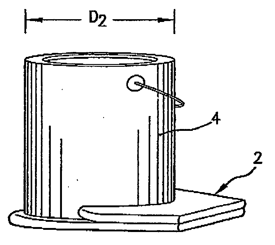
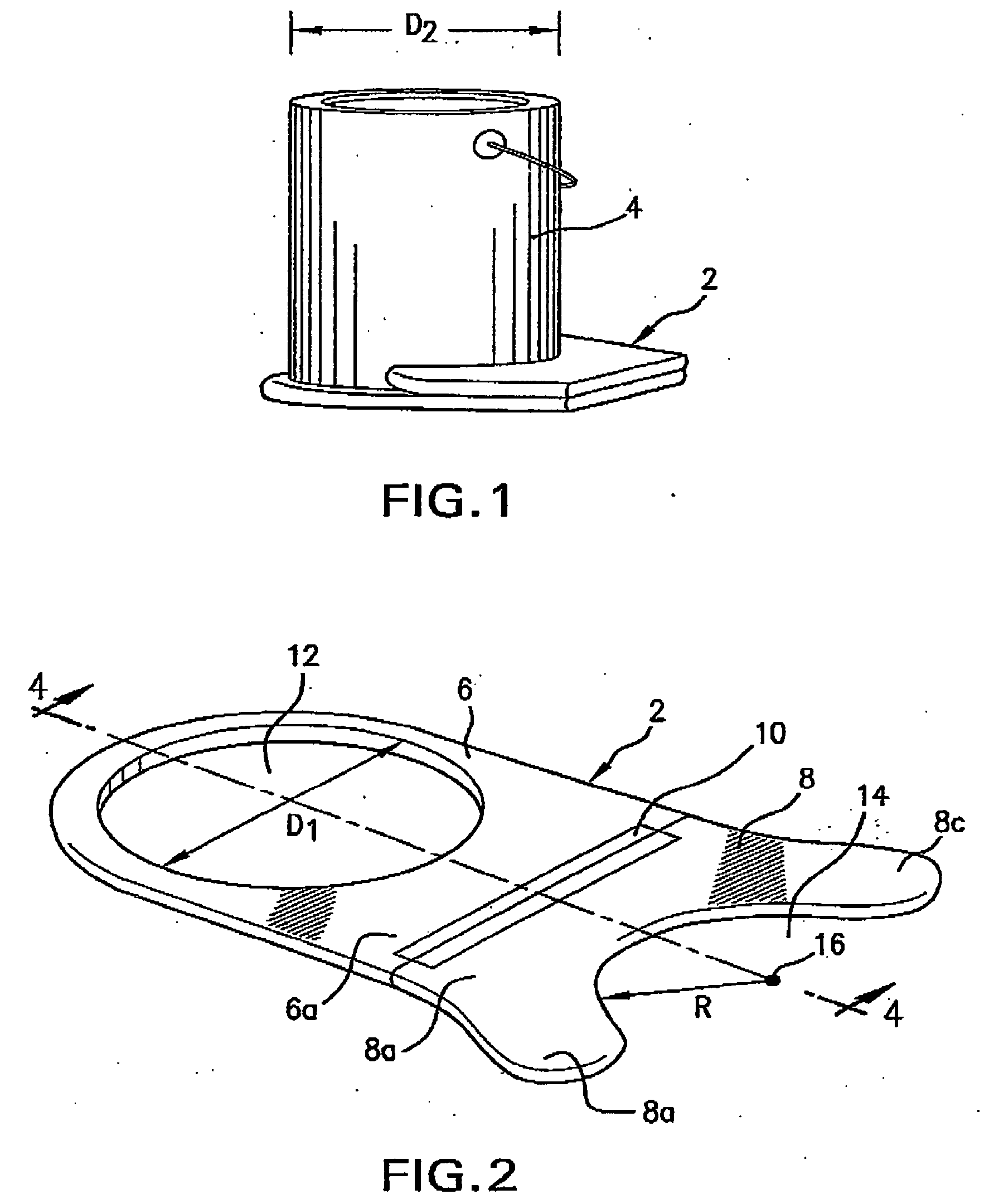
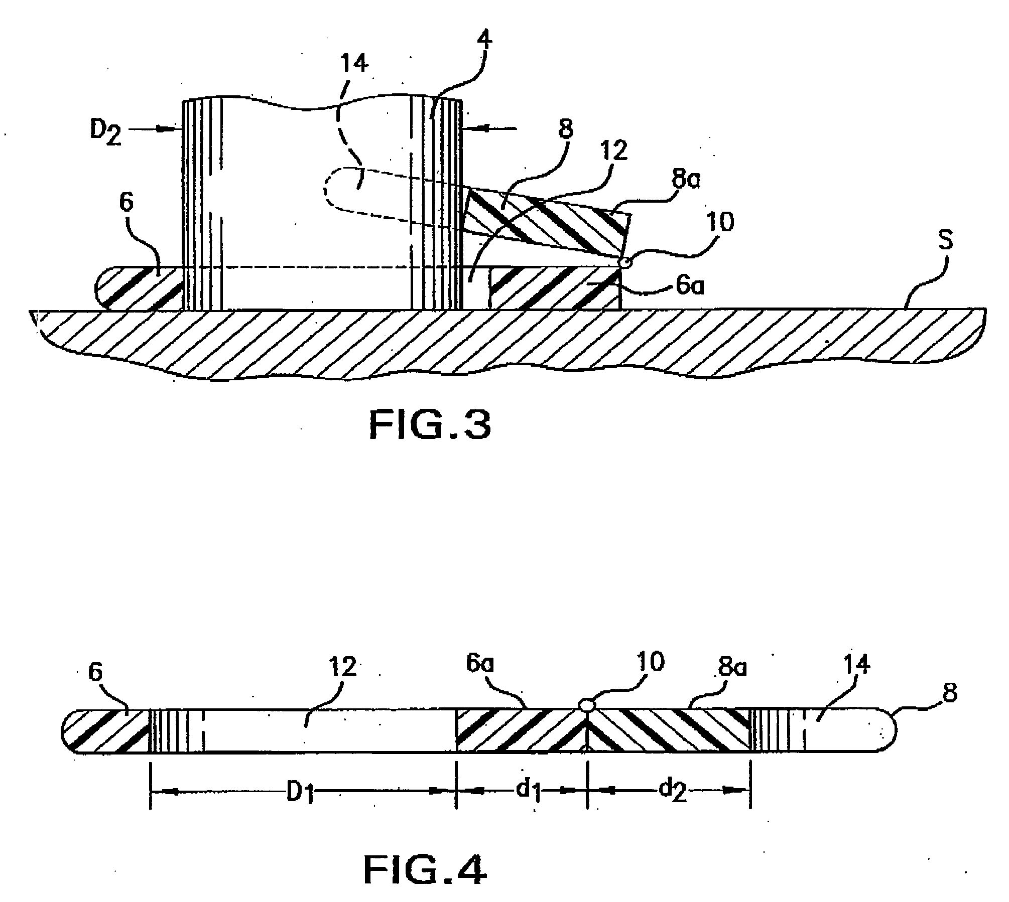
[0015] Referring first more particularly to FIGS. 1 and 2, the bucket stabilizing apparatus 2 of the present invention is designed to stabilize a large cylindrical bucket 4 during the mixing of the fluid contents thereof by conventional motor-operated or manual mixing means (not shown). The stabilizing apparatus includes a base member 6 and a support member 8 having adjacent straight edge portions 6a and 8a that are pivotally connected together by pivot means 10, specifically, a piano hinge. The base member is normally horizontal and contains a circular opening 12 having a diameter D1 that is slightly greater than the diameter D2 of the bucket 4. The edge of the support member 8 remote from the hinge 10 contains a semi-circular recess 14 having a radius R that is slightly less than one half of the diameter D1 of the opening 12. The center 16 of the radius R of the semi-circular recess 14 and the center of the circular opening 12 are contained in a common vertical plane extending lon...


PUM


Abstract

A two-part bucket stabilizing apparatus for use with cylindrical joint compound buckets or the like during the mixing of the contents thereof includes a horizontal base member containing an opening for receiving the bottom of the bucket, and a support member having a first edge portion pivotally connected with the base member, and a remote edge portion containing a semi-circular recess. The support member is pivotally operable from an initial horizontal position upwardly and inwardly toward a clamping position above the base portion in which the wall of the semi-circular recess is in clamping engagement with the outer circumferential wall surface of the bucket.

Description

CROSS REFERENCE TO RELATED APPLICATIONS [0001] In accordance with the provisions of 35 U.S. Code § 119(e)(1), this application claims priority of the Provisional Application No. 60 / 659,732 filed Mar. 9, 2005.BACKGROUND OF THE INVENTION [0002] 1. Field of the Invention [0003] A two-piece bucket stabilizing apparatus for use with cylindrical joint compound buckets or the like during the mixing of the contents thereof includes a horizontal base member containing an opening for receiving the bottom of the bucket, and a support member having a first edge portion pivotally connected with the base member, and a remote edge portion containing a semi-circular recess. The support member is pivotally operable from a horizontal position toward a clamping position above the base portion, whereupon the wall of the semi-circular recess is brought into clamping engagement with the outer circumferential wall surface of the bucket. [0004] 2. Description of Related Art [0005] Various types of devices ...

Claims


Application Information

Patent Timeline
Patent Type & Authority Applications(United States)
IPC IPC(8): A47G23/02B01F15/00
CPCB01F15/00733B01F2215/005B44D3/14B01F35/42B01F2101/30
Inventor GROSSE, JOEL H.
Owner GROSSE JOEL H
Learn More