Top feed droplet generator

Inactive Publication Date: 2006-09-14
EASTMAN KODAK CO
View PDF14 Cites 0 Cited by
  • Summary
  • Abstract
  • Description
  • Claims
  • Application Information

AI Technical Summary

Benefits of technology

[0005] The present embodiments are advantageous over the prior art because the ink jet printer

Problems solved by technology

Turbulence occurs in the smaller through bores and affects the stimulation performance of the drop let generator.
The turbulence problem also exists when at

Method used


Image

  • Top feed droplet generator
  • Top feed droplet generator
  • Top feed droplet generator

Examples


Example

[0014] The present embodiments are detailed below with reference to the listed Figures.

DETAILED DESCRIPTION OF THE INVENTION

[0015] The present description will be directed in particular to elements forming part of, or cooperating more directly with, apparatus in accordance with the present invention. It is to be understood that elements not specifically shown or described may take various forms well-known to those skilled in the art.

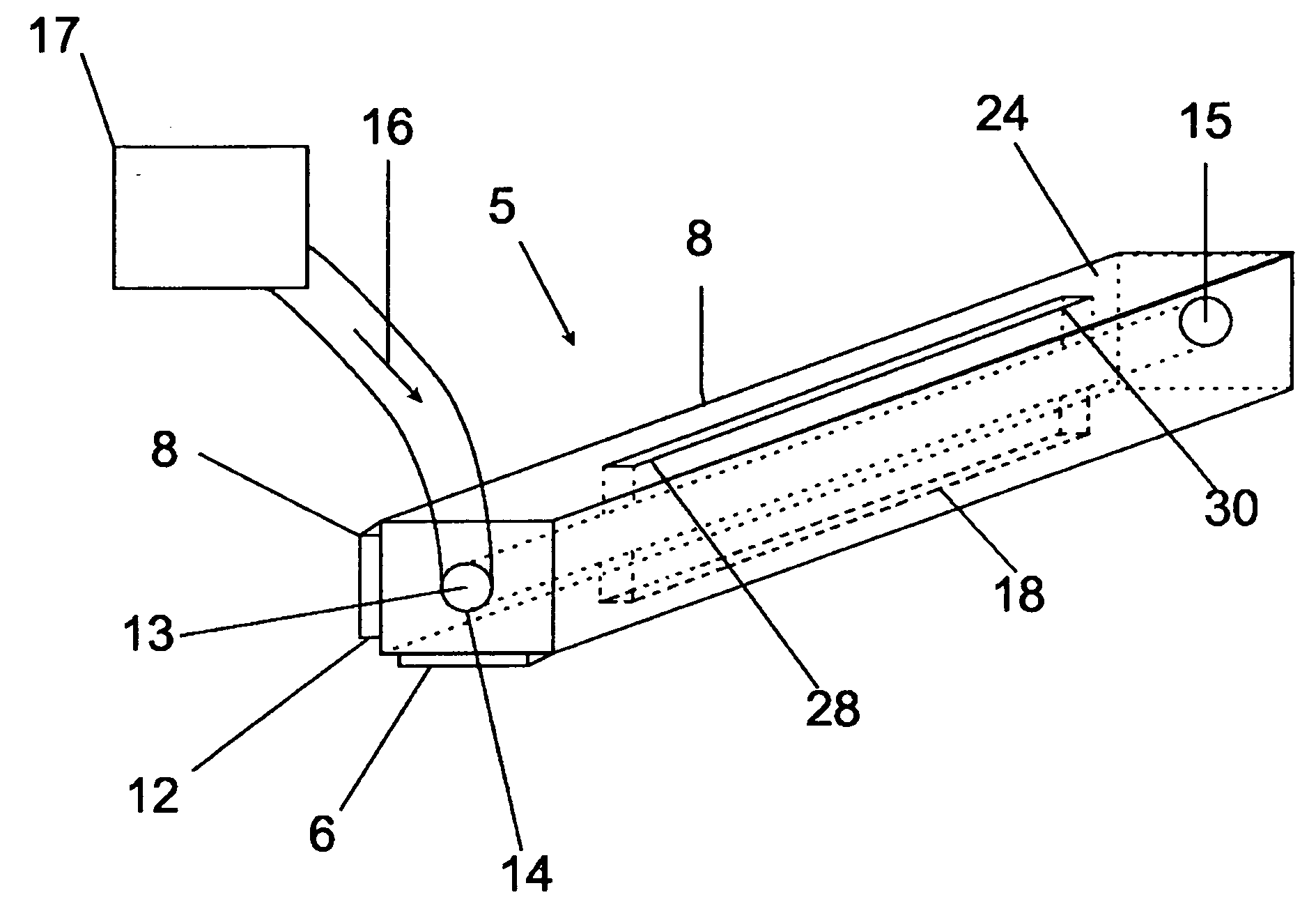
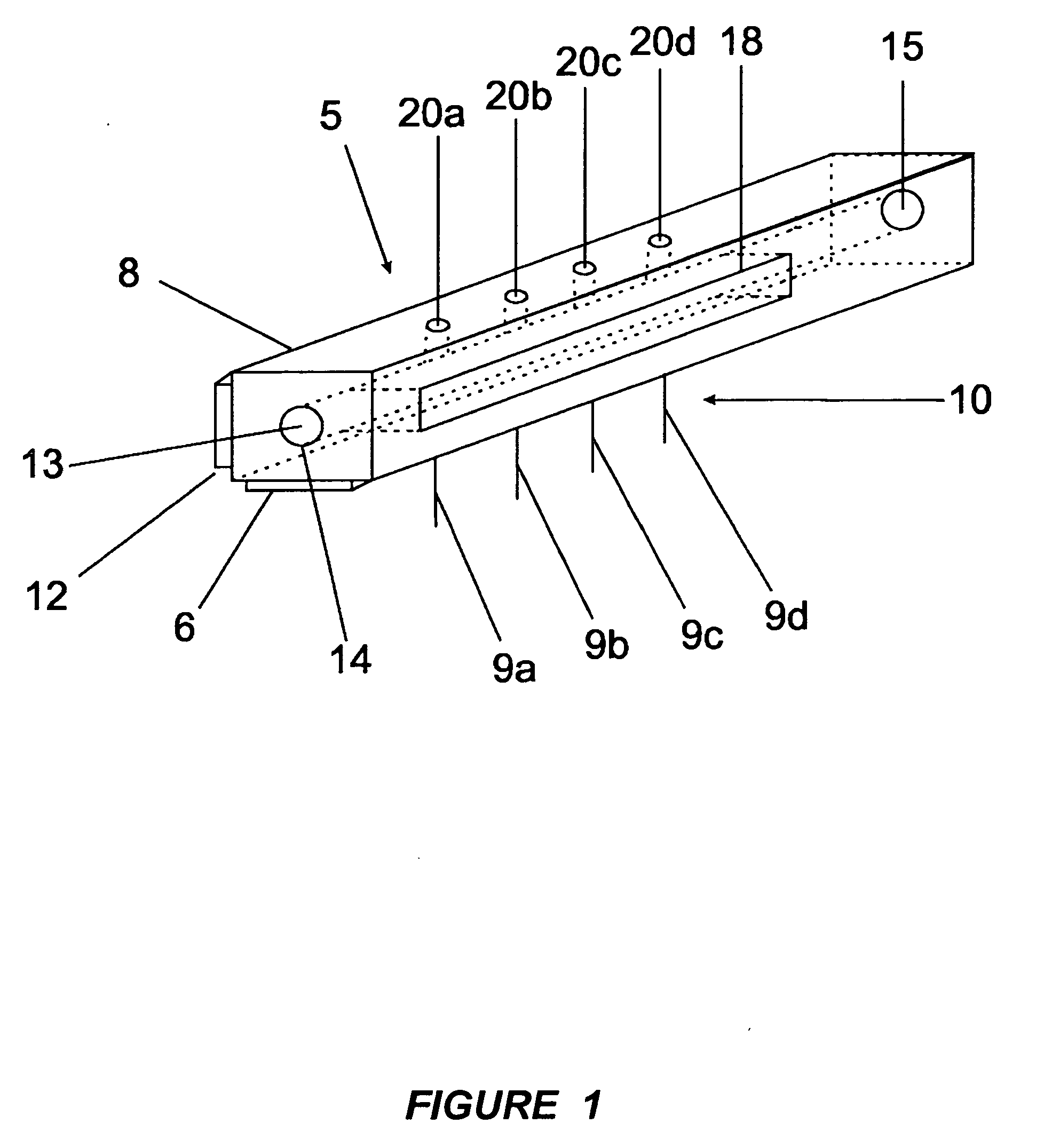
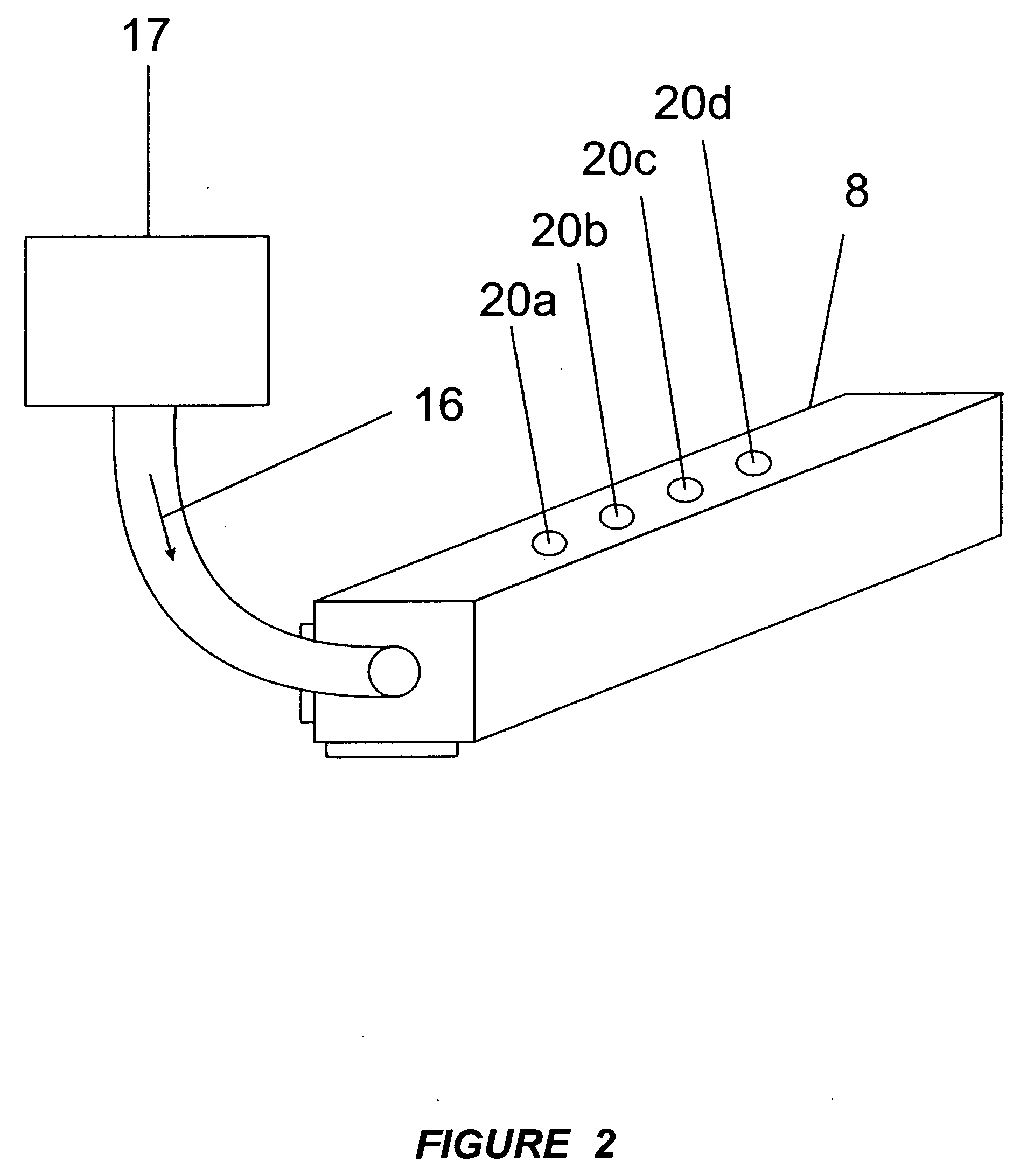
[0016] Turbulence in the cavity section of ink jets occurs as attempts are made to increase flow rates for ink jets. Traditionally, turbulence has been reduced by making the droplet generators throughbore larger. The larger sizes of the bore diameter of the droplet generator array results in a lower operating frequency for the droplet generator, which in turn means lower speed of operation.

[0017] The present embodiments provide the benefit of smaller bore diameters with the benefit of increased speed without the turbulence usually encountered. The em...


PUM


Abstract

An ink jet droplet generator body for an ink jet droplet generator comprising an orifice plate with a plurality of nozzles forming a jet array entails a throughbore with an entrance and exit port, the throughbore provides a path through that flows fluid from a fluid supply to the first slot. The first slot connects the throughbore to the orifice plate. One or more holes or a slot are located in the top of the generator body to direct fluid or a secondary source of fluid to the first slot and then the orifice plate.

Description

FIELD OF THE INVENTION [0001] The present embodiments relate generally to an improved droplet generator for ink jet printer. BACKGROUND OF THE INVENTION [0002] The overall thickness and height of continuous inkjet droplet generators must decrease to enable the frequency of droplet formation to increase. To further increase the droplet generation rates, the diameter of the bore through the droplet generator must decrease as well. This decrease conflicts with the need for increased amounts of ink flow required at higher frequencies. Turbulence occurs in the smaller through bores and affects the stimulation performance of the drop let generator. The turbulence problem also exists when attempting to fabricate a longer droplet generator with increased ink flow rates in order to supply the increased number of inkjets with a small through bore. [0003] A need exists for an increased amount of ink flowing to the droplet generator and while using a small bore. SUMMARY OF THE INVENTION [0004] ...

Claims


Application Information

Patent Timeline
IPC IPC(8): B41J2/175
CPCB41J2/175
Inventor BAUMER, MICHAEL F.
Owner EASTMAN KODAK CO
Why Eureka
Try Eureka