

Model hand for electromagnetic testing
a technology of electromagnetic testing and model hands, applied in the field of microwave test equipment, can solve the problems of loss of signal energy, complicated matters, and dramatic change in the performance of the antenna
- Summary
- Abstract
- Description
- Claims
- Application Information
AI Technical Summary
Problems solved by technology
Method used
Image

Examples
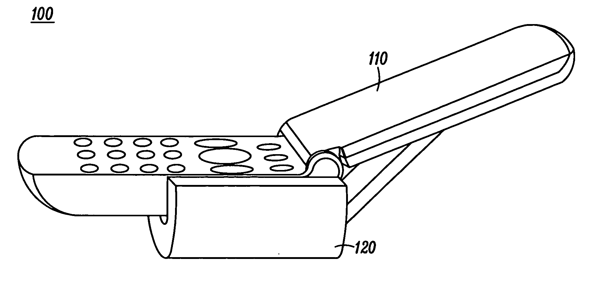
embodiment 120
[0022] The first preferred embodiment 120 has bulk “hand tissue” that extends to the top plane of the wireless communication device 110, and runs along a side of the device just as in a real human hand. A thumb-like member has been omitted and replaced by a simplified portion of the bulk hand / palm.
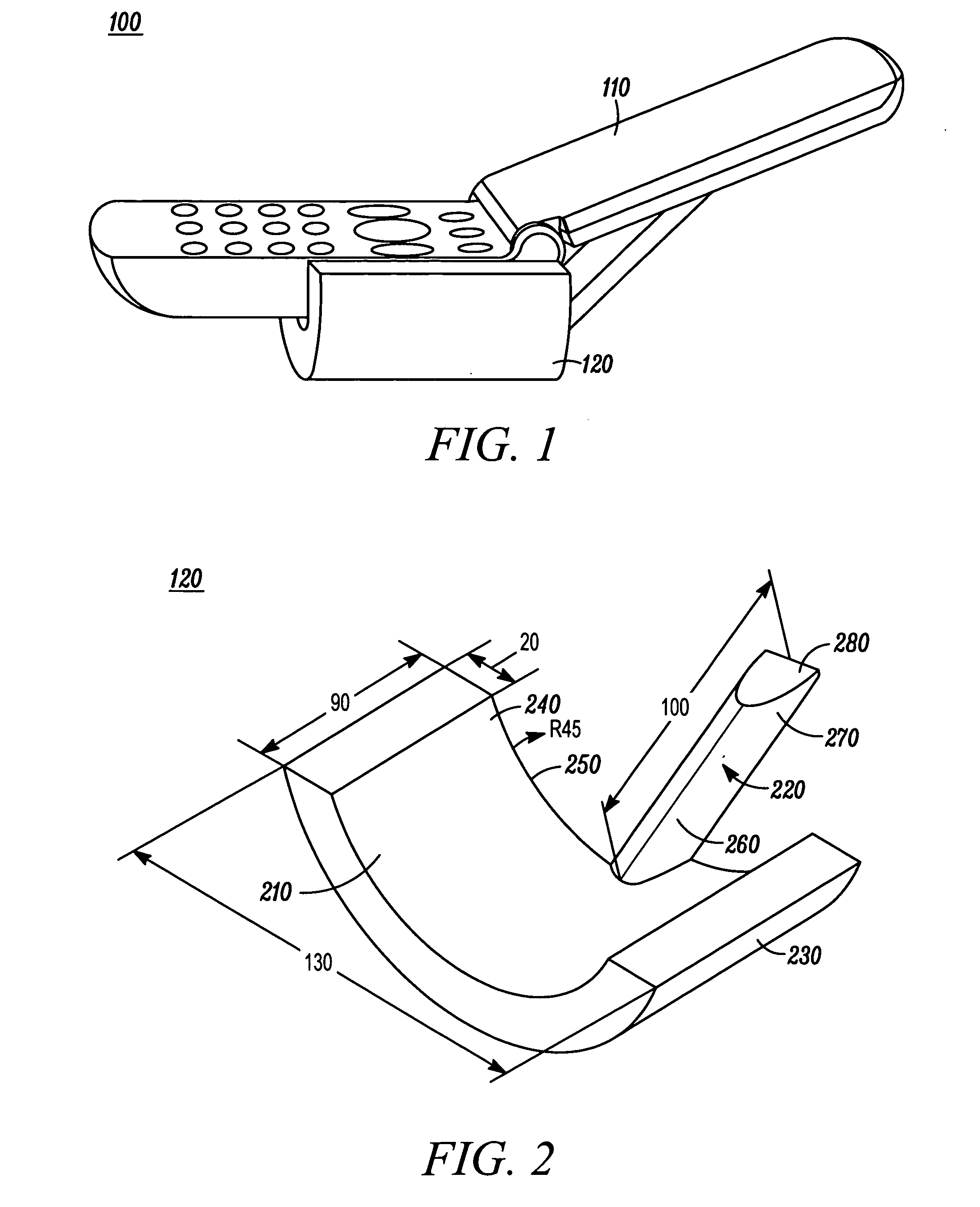
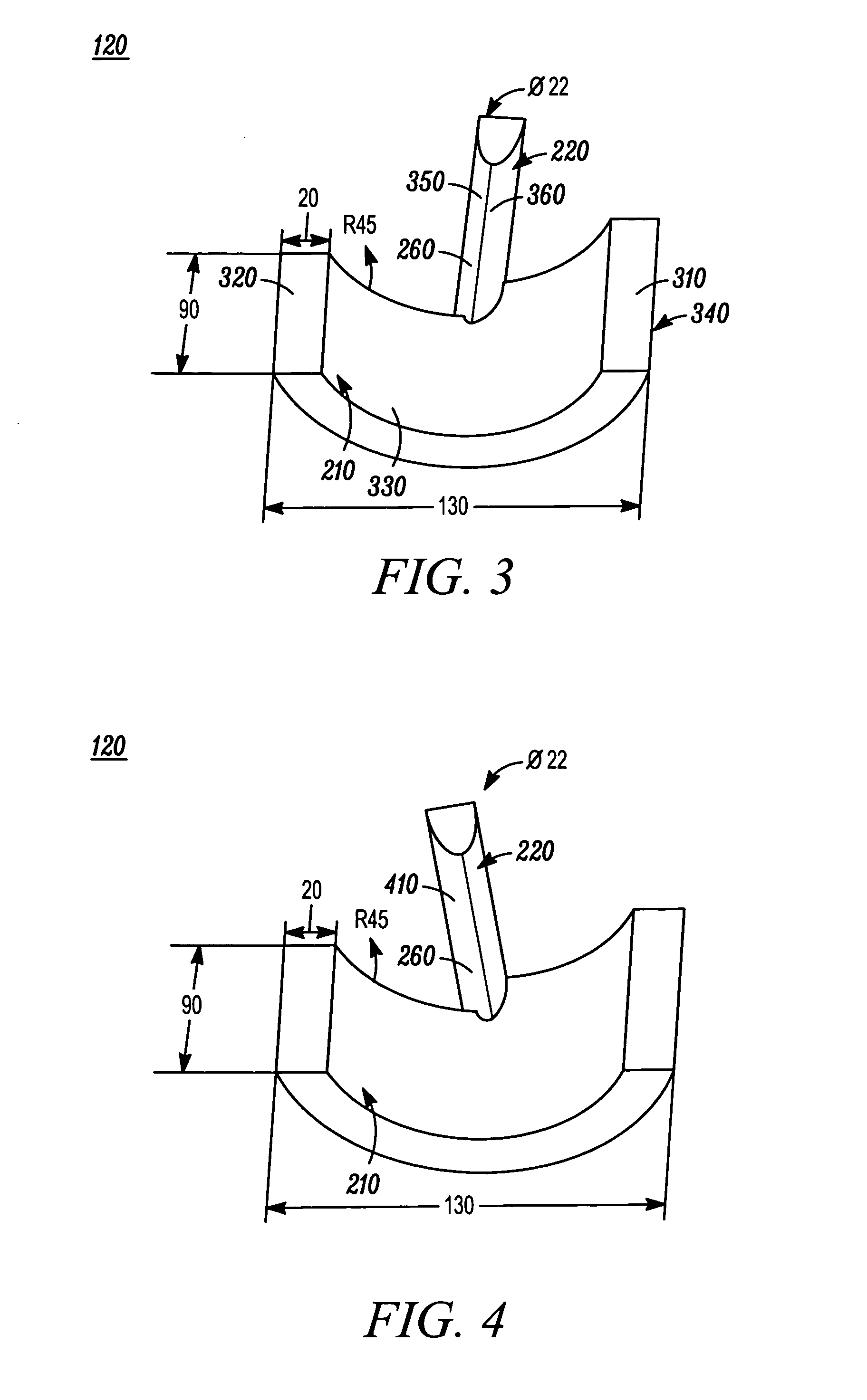
[0023] Referring to FIG. 2, the first embodiment 120 of the universal model hand comprises a cylindrical body 210 and an extending digit 220 extending from one side of the cylindrical body. The cylindrical body 210 has an outer surface 230 and an inner surface 240. The outer surface 230 has a semi-cylinder or half-cylinder form, and the inner surface 240 has a similar, yet smaller, semi-cylinder or half-cylinder form. The outer surface 230 had an arcuate shape, and the inner surface 240 follow the arcuate shape of the outer surface so that each location of the inner surface is generally equidistant from a closest location of the outer surface. The extending digit 220 has a rigid linear for...
second embodiment
[0034] The composition of the materials used to produce the embodiments of the present invention should be rigid enough to support a wireless communication device and have properties that minimize any interference with electromagnetic testing. For example, for the second embodiment described above, a silicone, carbon and aluminum composition specifically formulated to have RF dielectric properties of the aggregate hand tissues may be used for the external portion of the model hand, and a Delrin™ type plastic, with a diameter no more than 7.5 mm, may be used for the internal components 800 of the pointer finger.
[0035] For a third embodiment, the index or pointer digit may be removable. For example, referring to FIG. 2, the base end 260 of the extending digit 220 of the first embodiment may be removably coupled to the top side 250 of the cylindrical body 210. Likewise, referring to FIG. 7, the base end 790 of the dynamic digit (such as pointer digit 780) of the second embodiment may b...
PUM
 Abstract
Description
Claims
Application Information