
Bicycle shifter

a technology of shifters and bicycles, applied in the direction of cycle equipment, mechanical control devices, instruments, etc., can solve the problems of increased weight, discomfort of repeatedly adjusting the hand and finger between the two levers, and loss of control,

Active Publication Date: 2006-09-21
SRAM CORPORATION
View PDF14 Cites 65 Cited by
  • Summary
  • Abstract
  • Description
  • Claims
  • Application Information

AI Technical Summary

Benefits of technology

The present invention provides a bicycle shifter with a single control member movable in both pull and release directions to shift gears. The shifter includes a housing mountable to the handlebar of the bicycle, a takeup member movable in cable-pull and cable-release directions, and a drive mechanism for disengaging the takeup member from the ratchet wheel. The control member is biased towards a rest position and can be actuated in the shift direction to disengage the ratchet wheel and release the takeup member. The shifter also includes a holding pawl engageable with the ratchet wheel teeth to retain the takeup member in a selected gear position. The shifter provides both audible and tactile feedback to the rider and allows for gear shifts with a single control member.

Problems solved by technology

Disadvantages of a two-lever shifter include added weight and the discomfort of repeatedly maneuvering the hand and fingers between the two levers.
Although acceptable for some applications, discomfort and loss of control may result when shifting, as the rider maneuvers his hand and fingers to alternate sides of such a lever.

Method used


Image

  • Bicycle shifter
  • Bicycle shifter
  • Bicycle shifter

Examples


Embodiment Construction

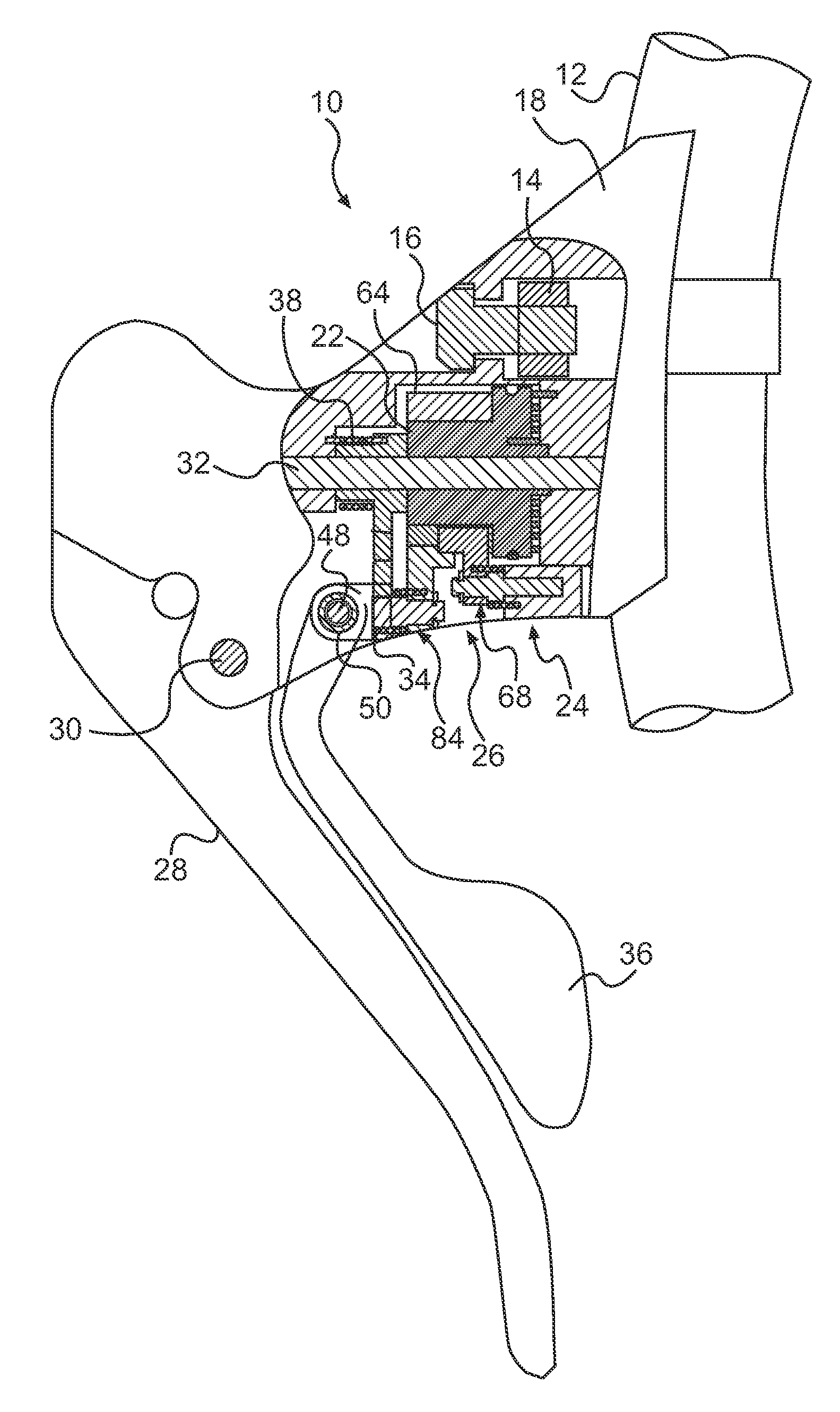
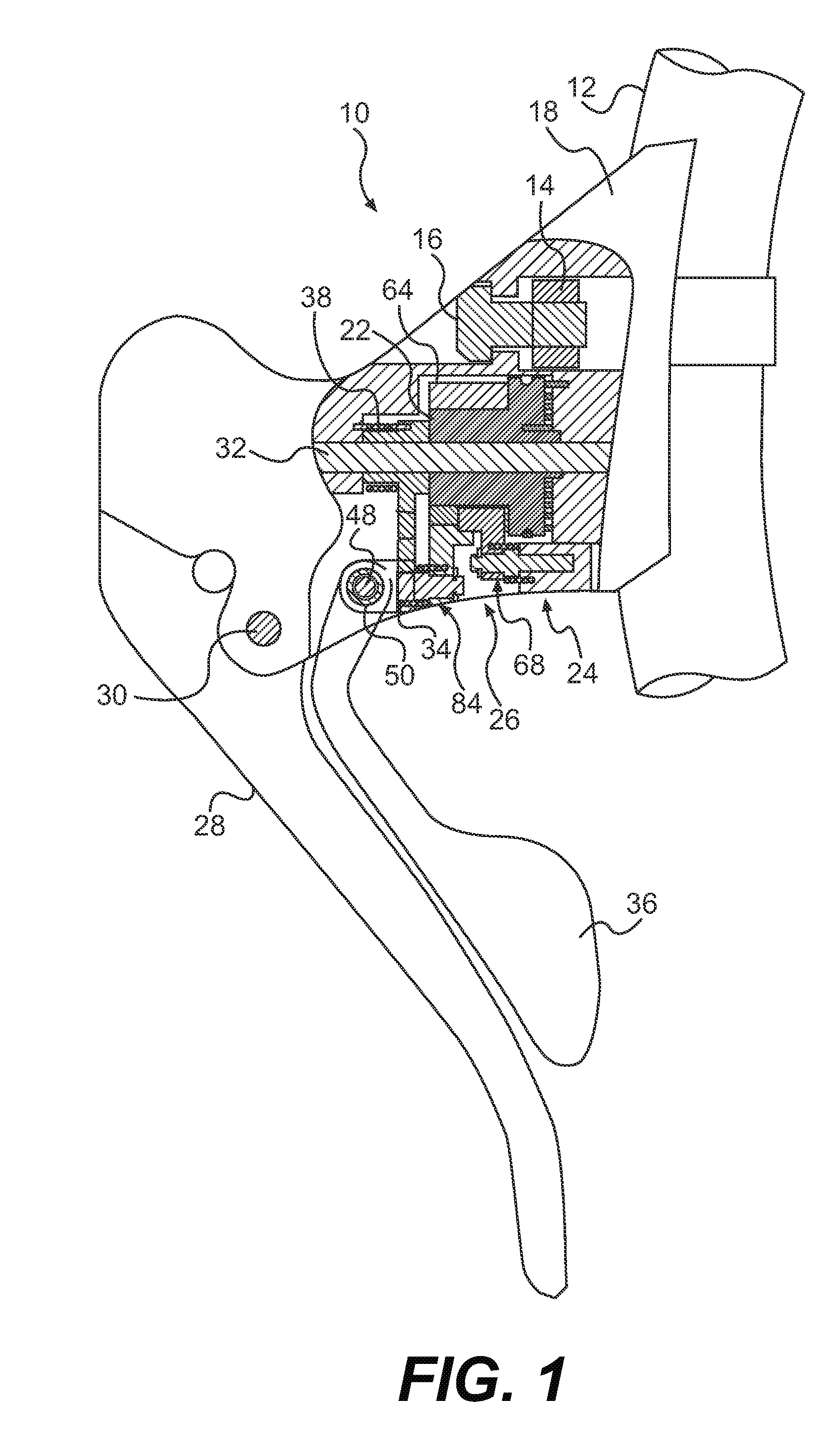
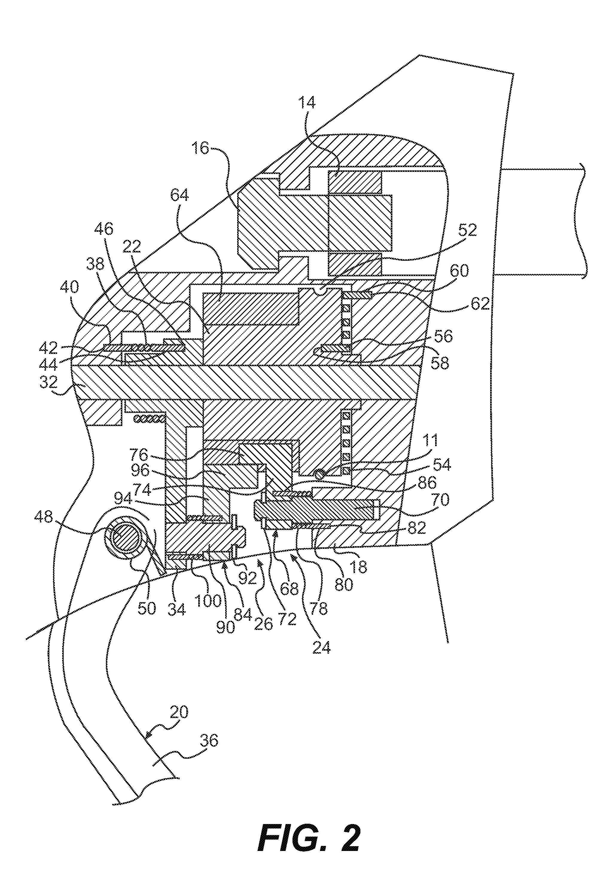
[0015]FIGS. 1-4 illustrate a bicycle shifter 10 according to one embodiment of the present invention. The bicycle shifter 10 pulls or releases a control cable 11 connected to a gear change mechanism (not shown) to shift between various gear positions. The gear change mechanism may be a derailleur, or other external or internal gear change devices. The bicycle shifter 10 is mounted to a handlebar 12 by a clamp 14 and a bolt 16. The bicycle shifter 10 shown is a road shifter for use on a road bike. However, similar shifters may be adapted for use on other types of bicycles, including mountain bikes. In this embodiment, the bicycle shifter 10 generally includes a housing 18, a control member 20, a takeup member 22, a holding mechanism 24 and a drive mechanism 26. In this embodiment, the shifter 10 is integrated with a brake lever 28. The brake lever 28 pivots about a brake pivot 30, pulling a brake cable (not shown) to slow the bicycle. Alternatively, the brake lever 28 may be formed s...


PUM


Abstract

A bicycle shifter for pulling and releasing a control cable connected to a gear change mechanism that includes a housing mountable to a handlebar, a takeup member, a control member, a holding mechanism and a release mechanism. The takeup member is movable for pulling the control cable in a cable-pull direction and releasing the control cable in a cable-release direction. The control member is movable in a shift direction from a rest position for a first shift movement to permit motion of the takeup member in the cable-release direction. The first shift movement corresponds to a single gear change. The control member is movable in the shift direction from the rest position for a second shift movement to move the takeup member in the cable-pull direction. The second shift movement corresponds to a plurality of gear changes. The second shift movement is greater than the first shift movement. The control member is biased toward the rest position. The holding mechanism retains the takeup element in a selected gear position. The drive mechanism is operable for releasing the holding mechanism from the takeup member and for moving the takeup member in response to actuation of the control member.

Description

BACKGROUND OF THE INVENTION [0001] The present invention relates to bicycle shifters, and more particularly, to a bicycle shifter having a single control lever movable in one direction for pulling and releasing a control cable. [0002] Conventional bicycle shifters have been designed to include separate control levers, one for pulling, another for releasing the control cable. Disadvantages of a two-lever shifter include added weight and the discomfort of repeatedly maneuvering the hand and fingers between the two levers. Bicycle shifters have also been designed to include a single lever operable in two directions, one to pull, the other to release the control cable. Although acceptable for some applications, discomfort and loss of control may result when shifting, as the rider maneuvers his hand and fingers to alternate sides of such a lever. SUMMARY OF THE INVENTION [0003] The present invention provides a bicycle shifter having a single control member movable in a shift direction to...

Claims


Application Information

Patent Timeline
Patent Type & Authority Applications(United States)
IPC IPC(8): G05G11/00
CPCB62M25/04Y10T74/20287Y10T74/20438
Inventor JORDAN, BRIANSHIPMAN, CHRISTOPHERWESLING, KEVIN
Owner SRAM CORPORATION
Learn More