Condenser arrangement

a technology of condenser and condenser body, which is applied in the direction of vehicle components, transportation and packaging, propulsion parts, etc., can solve the problems of time-consuming and labor-intensive condenser mounting and detachment, and limit the design capabilities of the front end portion of the vehicle, so as to achieve easy and quick mounting and detachment

Inactive Publication Date: 2006-09-21
NISSAN TECHN CENT NORTH AMERICA
View PDF7 Cites 32 Cited by
  • Summary
  • Abstract
  • Description
  • Claims
  • Application Information

AI Technical Summary

Benefits of technology

[0008] One object of the present invention is to provide a condenser arrangement for a vehicle in which the condenser is easily and quickly mounted to and detached from a vehicle support structure without using a fastening tool.

Problems solved by technology

The conventional condenser arrangement is time consuming for mounting and detaching the condenser from the vehicle support structure for assembly and service.
Also, this type of conventional condenser arrangement limits the design capabilities of the front end portion of the vehicle because the upper brackets, which are attached to the vehicle support structure by the fasteners, have to be designed to provide sufficient strength.

Method used


Image

  • Condenser arrangement
  • Condenser arrangement
  • Condenser arrangement

Examples


Embodiment Construction

[0027] Selected embodiments of the present invention will now be explained with reference to the drawings. It will be apparent to those skilled in the art from this disclosure that the following descriptions of the embodiments of the present invention are provided for illustration only and not for the purpose of limiting the invention as defined by the appended claims and their equivalents.

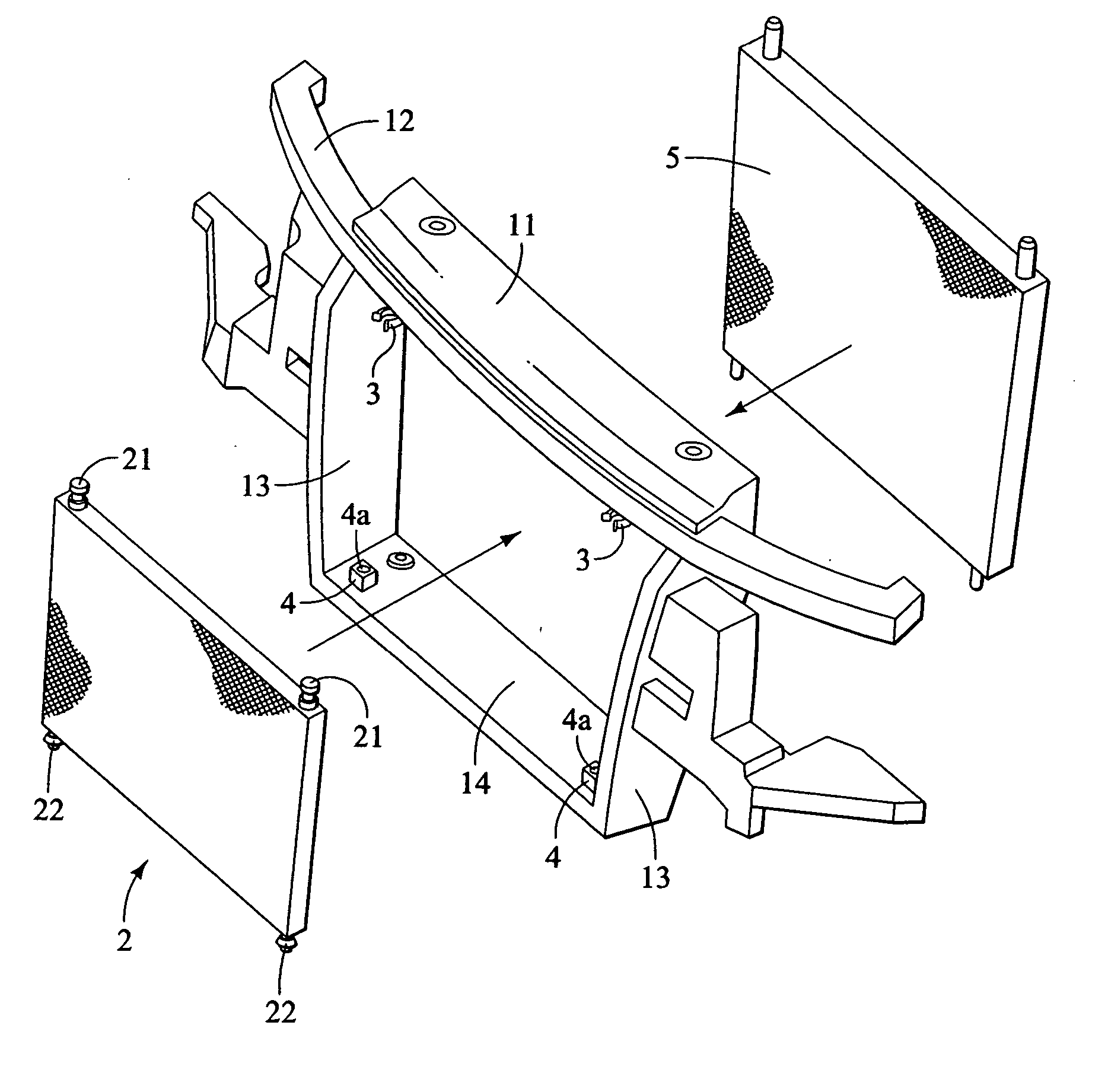
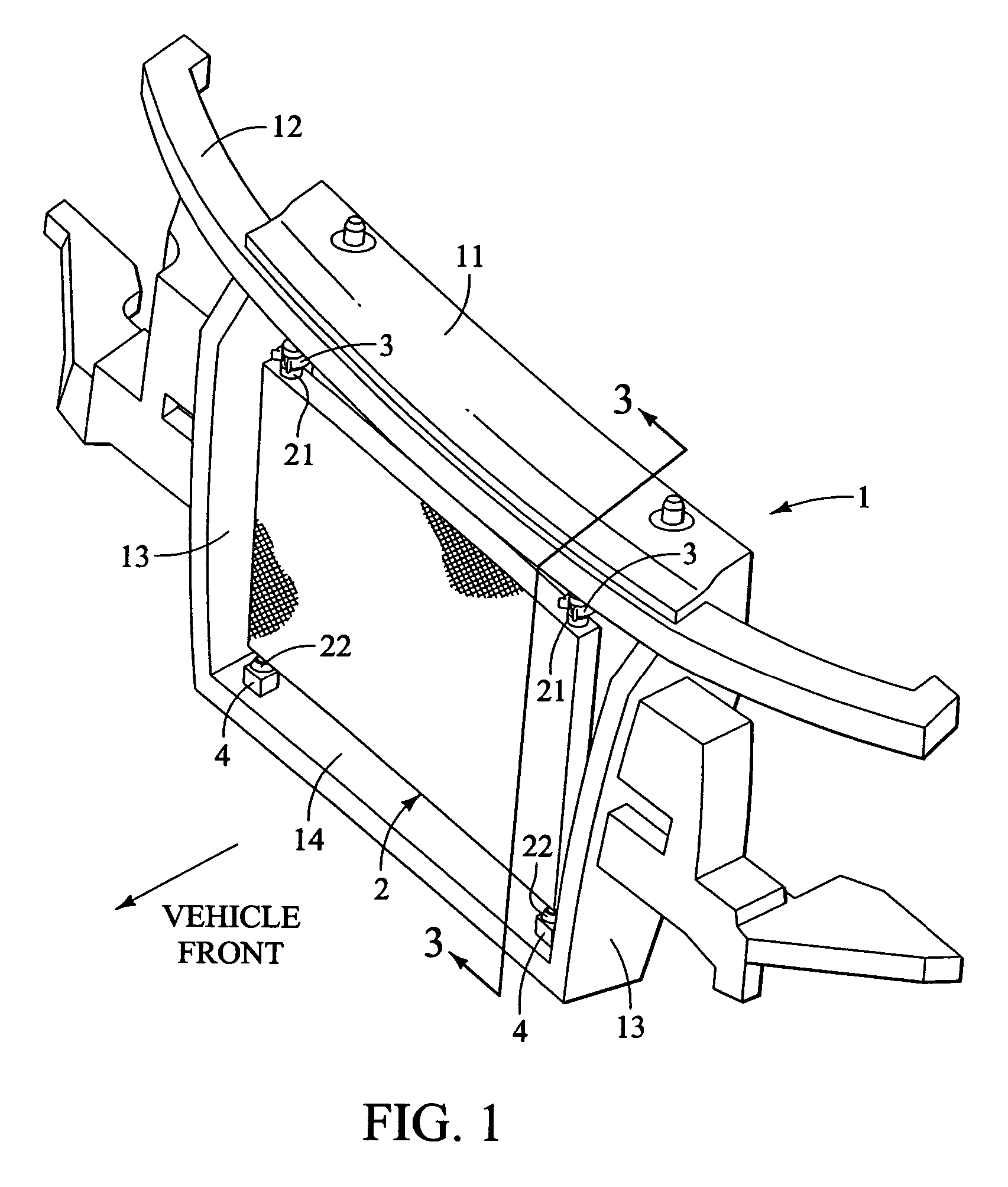
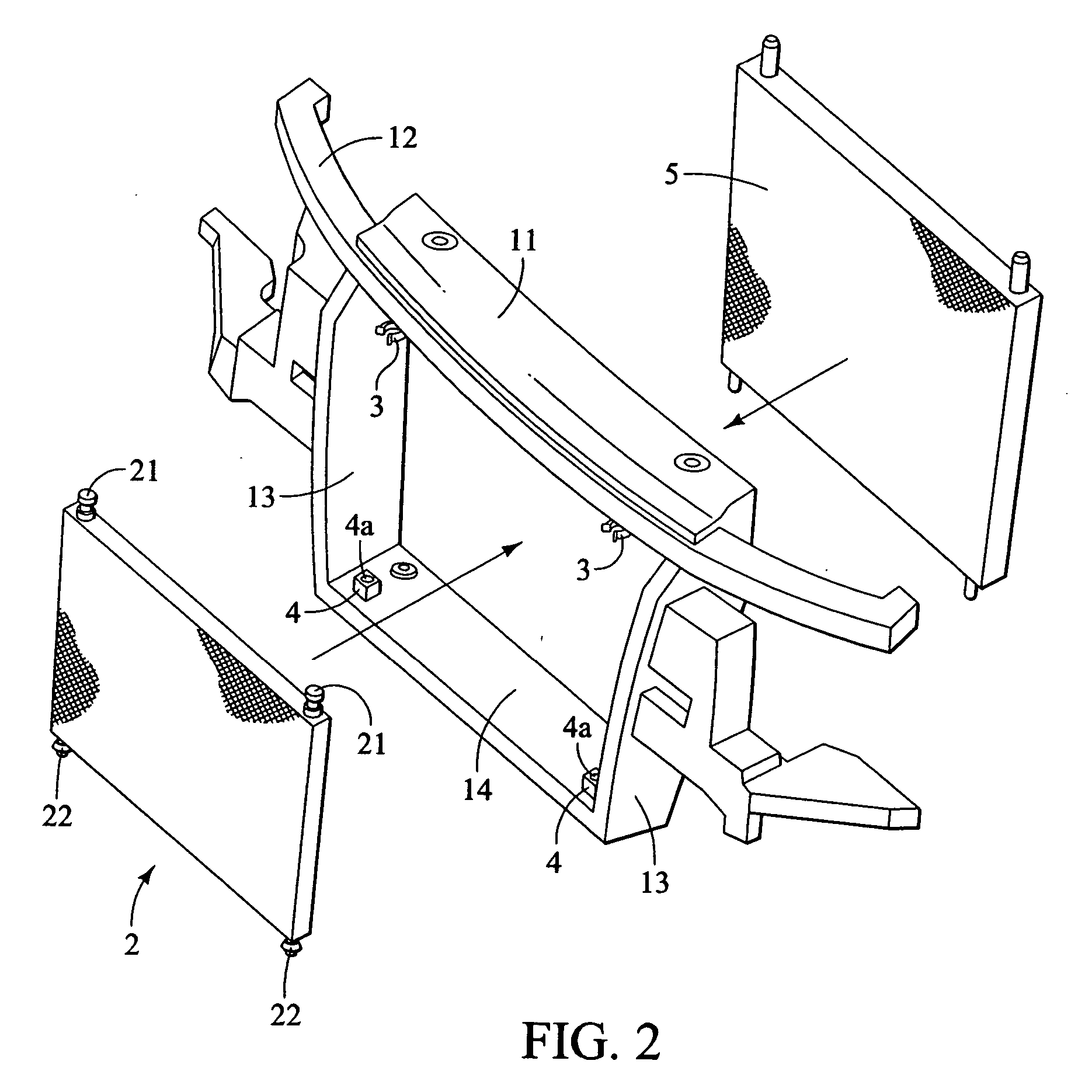
[0028] Referring initially to FIGS. 1 and 2, a condenser arrangement is illustrated in accordance with a preferred embodiment of the present invention. As seen in FIGS. 1 and 2, the condenser arrangement of this embodiment is preferably incorporated in a vehicle front end module that is configured and arranged to be disposed in a front portion of a vehicle. The vehicle front end module includes a vehicle support structure 1 that constitutes the framework configured and arranged to incorporate a plurality of brackets for mounting various vehicle components that are disposed in the front end portio...


PUM


Abstract

A condenser arrangement for a vehicle is provided that comprises a vehicle support structure, upper and lower condenser coupling structures and a condenser. The upper and lower condenser coupling structures are fixedly coupled to upper and lower mounting portions of the vehicle support structure. The condenser has a lower attachment structure releasably engaged with the lower condenser coupling structure, and an upper attachment structure releasably engaged with the upper condenser coupling structure. The upper and lower condenser coupling structures are configured and arranged with respect to the upper and lower attachment structures, respectively, to form a pair of toolless connections between the condenser and the vehicle support structure for repeatable connection and detachment of the condenser to and from the vehicle support structure with the toolless connections having retaining forces greater than vibrationally inducing forces occurring during operation of the vehicle.

Description

BACKGROUND OF THE INVENTION [0001] 1. Field of the Invention [0002] The present invention generally relates to a condenser arrangement for a vehicle. More specifically, the present invention relates to a condenser mounting structure in which a condenser is mounted to a vehicle support structure with a plurality of toolless connections. [0003] 2. Background Information [0004] In some conventional condenser arrangements that are utilized in a vehicle, a condenser is mounted to a vehicle support structure by using a pair of upper brackets and a pair of lower brackets. More specifically, the upper and lower brackets are attached to a radiator core support member or a bolster member of the vehicle support structure. The lower brackets are usually mounted to the radiator core support member using spot weld since the lower brackets usually do not need to be removed for disassembly and assembly of the condenser for service. On the other hand, the upper brackets are usually attached by using...

Claims


Application Information

Patent Timeline
Patent Type & Authority Applications(United States)
IPC IPC(8): B60K11/04
CPCB60K11/04
Inventor VANDEKERKHOF, NATHAN
Owner NISSAN TECHN CENT NORTH AMERICA
Why Eureka
Try Eureka