Chipper knife

a technology of chipper blade and chipper head, which is applied in the direction of manufacturing tools, cocoa, grain treatment, etc., can solve the problems of machine jamming, the knife is not in position, and the finished lumber is defectiv

Inactive Publication Date: 2006-09-21
COE NEWNES MCGEHEE USA
View PDF24 Cites 11 Cited by
  • Summary
  • Abstract
  • Description
  • Claims
  • Application Information

AI Technical Summary

Problems solved by technology

One of the main problems with the knife/counter-knife configuration happens when wood fiber is forced between the two parts during operation.
The contaminates in this area can force a gap between the knife and counter-knife causing the knife to move out of position.
A deeper cut is produced by the out of position knife which may lead to a defect in the finished lumber.
The knife's movement over time may also cause the top knife clamp to bend or break which can lead to machine jam-ups, operational downtime, equipment dam...

Method used


Image

  • Chipper knife
  • Chipper knife
  • Chipper knife

Examples


Embodiment Construction

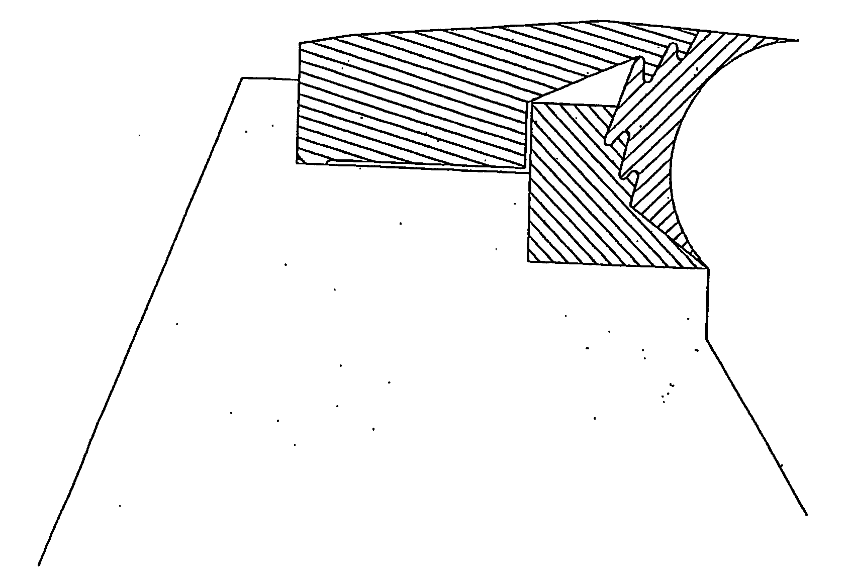
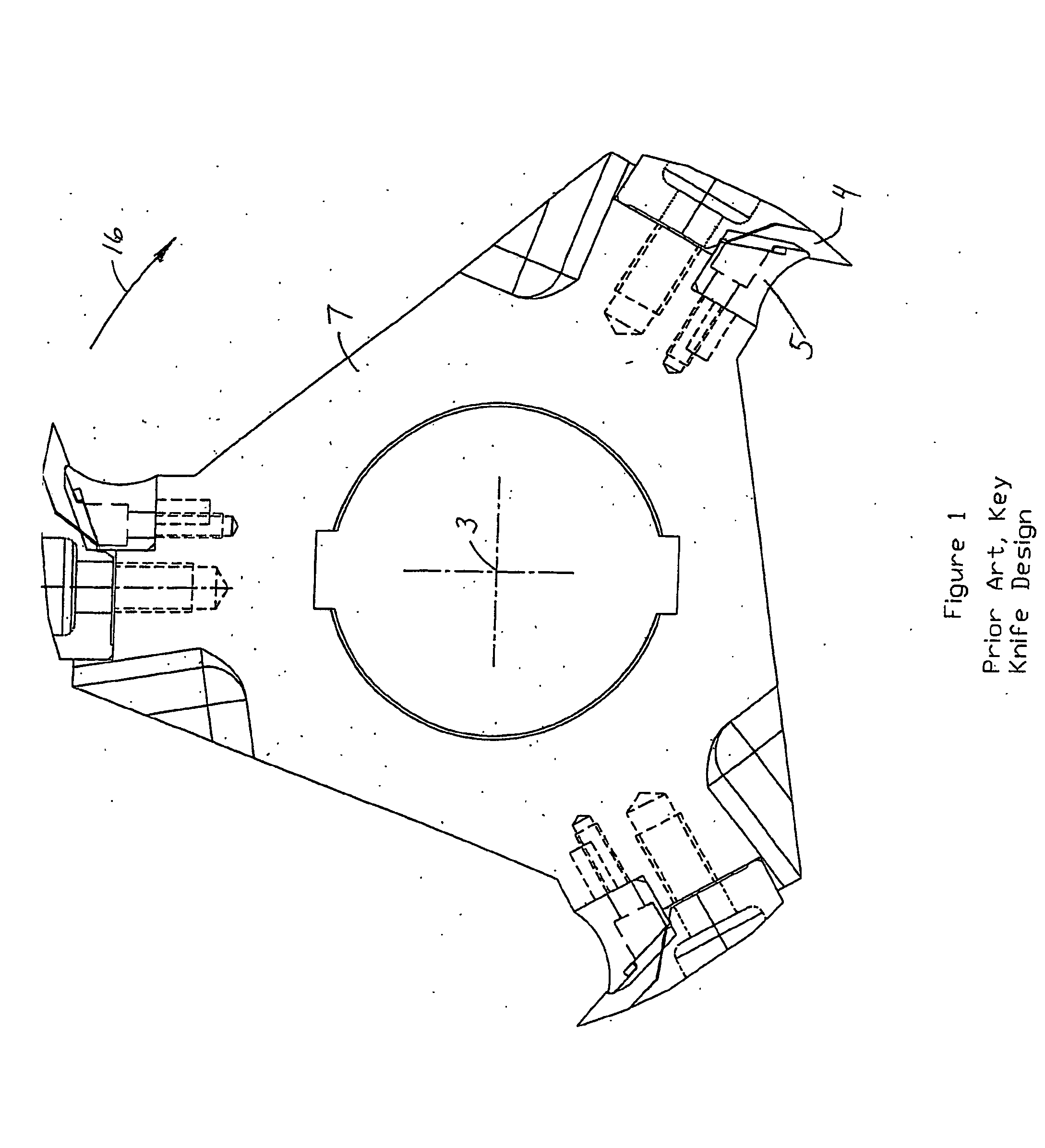
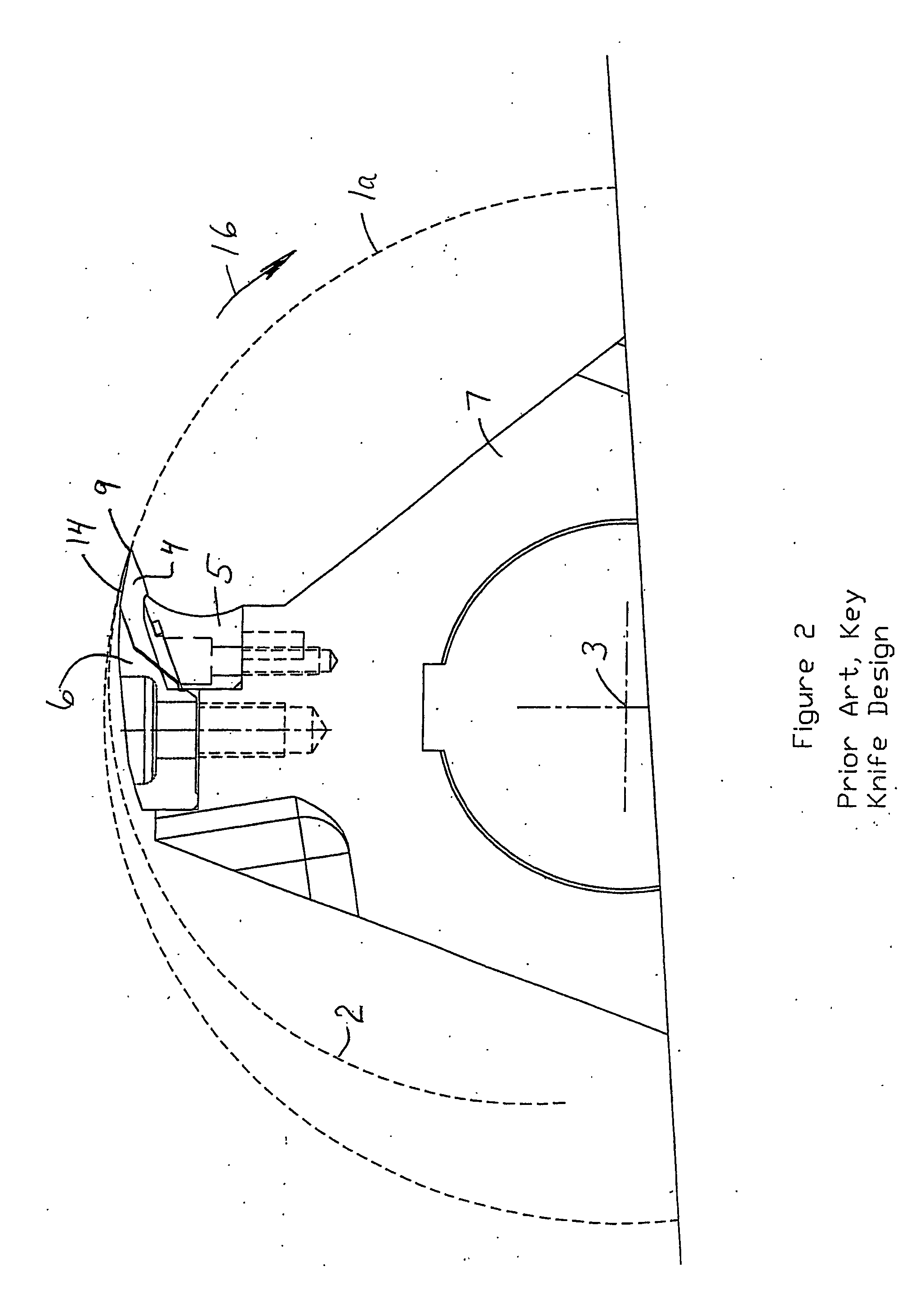
[0042] In one preferred embodiment, a double-edged reversible knife 4 with a fully exposed chip deflecting and shaping surface 13 between the two cutting edges 9. The chipper knife and counter-knife in prior art configurations are replaced in the new invention by a single one-piece knife 4 that cuts, deflects and shapes the wood chips. The one-piece knife 4 is held in position by interlocking top and bottom clamps 6 and 8 respectively that are attached to the chipper head 7. The cutting edge is, in this embodiment, defined as other than parallel to the chipper head axis 3 and lying at least substantially along a cylindrical surface of revolution 12 centered on the chipper head axis 3 as seen in FIGS. 4 through 7. In this preferred embodiment, not intended to be limiting, reversible knife 4 has two v-shaped cutting edges 9. Fully exposed chip deflecting and shaping surface 13 extends between these edges. The cutting edge falls along cylindrical surface of revolution 12 centered on th...


PUM


Abstract

A chipper knife (4) for mounting to a rotatable chipper head (7) includes a body having first and second cutting edges (9), a continuous chip deflecting and shaping surface (13) extending between the first and second cutting edges, and a mounting portion to permit the body to be mounted to the rotatable chipper head for rotation in a rotary direction.

Description

FIELD OF THE INVENTION [0001] This invention relates to the field of chipping heads and in particular to chipper knives of improved design. BACKGROUND OF THE INVENTION [0002] As used herein, like characters of reference denote corresponding parts in each illustration. Thus, in wood chipping machinery, a rotating chipper head 7, rotating in direction 16, accepts replaceable knives 4 and is used for shaping a log 1 traveling in direction A to permit downstream processing. Typically multiple chipper heads are positioned together on a common shaft and make up a small portion of larger log processing machinery. The axis of rotation 3 of the chipper head is generally perpendicular to the direction of movement of the log being processed. FIGS. 1 and 2 show a chipper head 7 with chipper knives 4 and associated clamping devices of prior art design. The replaceable chipping knives are typically of a design that provides for two sharp cutting edges 9 per piece as shown in cross section in FIG....

Claims


Application Information

Patent Timeline
IPC IPC(8): B02C18/18B27G13/10B27L11/00
CPCB27G13/10B27L11/005
Inventor MCGEHEE, RONALD
Owner COE NEWNES MCGEHEE USA
Why Eureka
Try Eureka