
Digital camera

a digital camera and lens interchange technology, applied in the field of digital cameras, can solve the problems of unfavorable control, unnecessary back and forth focusing lens, and inability to readily achieve focus, etc., and achieve the effect of burdening the user with no special operation

Inactive Publication Date: 2006-09-21
KONICA MINOLTA PHOTO IMAGING
View PDF1 Cites 23 Cited by
  • Summary
  • Abstract
  • Description
  • Claims
  • Application Information

AI Technical Summary

Benefits of technology

[0016] A principal object of the present invention is to provide a digital camera that burdens the user with no special operation when the lens is changed.
[0017] Another object of the present invention is to provide a digital camera capable of performing appropriate automatic focusing control even when the lens is changed.
[0018] Yet another object of the present invention is to provide a digital camera having an electronic viewfinder which digital camera is capable of performing appropriate electronic viewfinder display even when the lens is changed.
[0019] Still another object of the present invention is to provide a digital camera capable of performing appropriate electronic viewfinder display and appropriate contrast AF and in which no offensive noise is caused from the lens driving mechanism when an intra-body motor driven lens is attached to the camera.

Problems solved by technology

When this is done, however, the following problem newly arises: Currently, two kinds of taking lenses exist for single-lens reflex cameras.
That is, even though it is attempted to move the focusing lens to the focus position while repetitively calculating the contrast of the image, since the lens couplers have the play, control cannot be performed as desired, and there are cases where the focusing lens unnecessarily moves back and forth until reaching the focus position.
Naturally, even when the one-shot AF is performed, focus cannot be readily achieved.
When this occurs, since the focus position of the live view image moves back and forth as the focusing lens moves back and forth, the live view image is poor as the viewfinder image.
In addition, since the focusing lens is frequently driven back and forth, noises are caused from the lens driving mechanism such as the motor and the play of the lens couplers and such noises are offensive to the user.
To handle this problem, it is necessary for the user to make a judgment that the live view display is not selected or that the contrast AF is not driven according to the kind of the taking lens, which burdens the user with a special operation.

Method used


Image

  • Digital camera
  • Digital camera
  • Digital camera

Examples


first embodiment

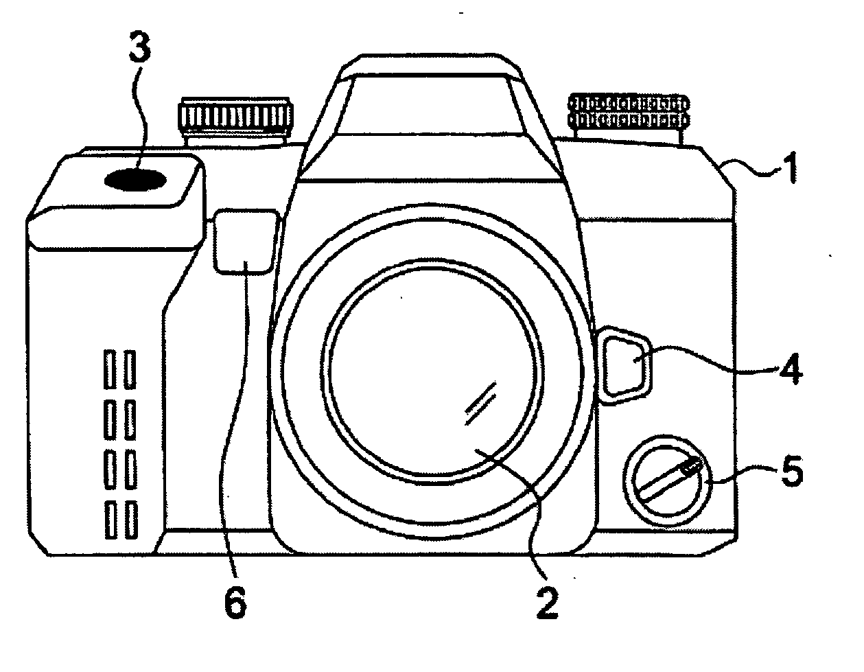
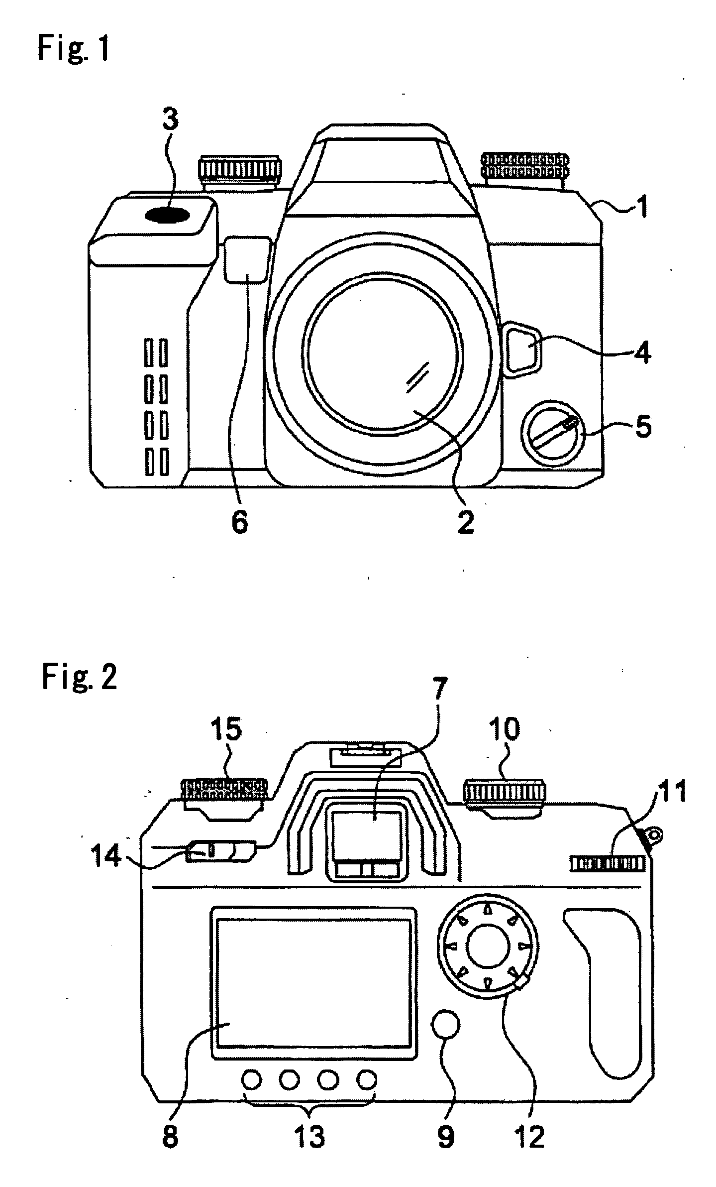
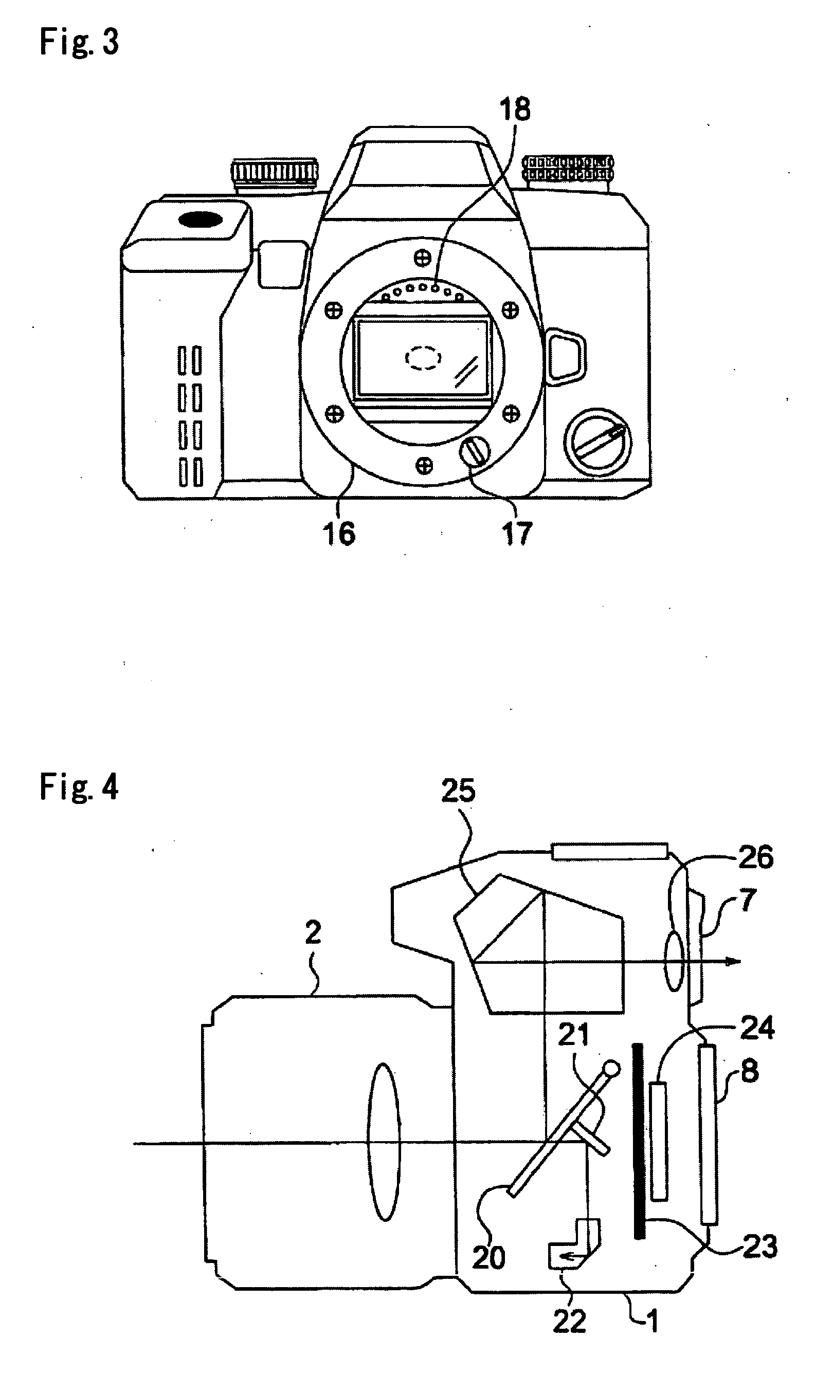
[0054] A digital camera according to the first embodiment is a digital single-lens reflex camera in which the taking lens is interchangeable, and has an optical viewfinder in which the light ray having passed through the taking lens is directed toward a pentaprism by a quick return mirror and is viewed through the eyepiece, and an electronic viewfinder in which an image capturing preparation image (live view image) taken by the image sensor is displayed on the LCD (“live view display”) before an image to be recorded is taken (photographing for recording). The user selects either the optical viewfinder or the electronic viewfinder. As the taking lens, both an intra-lens motor driven lens having a motor for driving a focusing lens in the lens, and an intra-body motor driven lens that performs focusing by the power of a motor for driving the focusing lens in the camera body are attachable.

[0055]FIG. 1 is a front view of the digital camera according to the first embodiment of the prese...

second embodiment

[0087] Since the structure of the hardware of the digital camera according to a second embodiment of the present invention is the same as that of the first embodiment, the description of the mechanical structure of the digital camera is omitted, and only the block diagram shown in FIG. 8 and the control sequence shown in FIG. 11 will be described.

[0088]FIG. 8 is a block diagram of the present embodiment. In this block diagram, the block diagram of only the camera body is shown, and the block diagram of the attached lens is omitted. In FIG. 8, the elements having similar functions to those of FIG. 6 are denoted by the same reference numerals. The present embodiment is different from the first embodiment only in the contents of the control CPU 41. Therefore, only the contents of the control CPU 41 will be described in this embodiment.

[0089] Reference numeral 44 represents a lens determining unit, which is the same as that of the first embodiment. The lens determining unit 44 makes a...

third embodiment

[0115] Since the structure of the hardware of the digital camera according to a third embodiment of the present invention is the same as that of the first embodiment, the description of the mechanical structure of the digital camera is omitted, and only the block diagram shown in FIG. 9 and the control sequence shown in FIG. 12 will be described.

[0116]FIG. 9 is a block diagram of the present embodiment. In this block diagram, the block diagram of only the camera body is shown, and the block diagram of the attached lens is omitted. In FIG. 9, the elements having similar functions to those of FIGS. 6 and 7 are denoted by the same reference numerals. The present embodiment is different from the first embodiment only in the contents of the control CPU 41. Therefore, only the contents of the control CPU 41 will be described in this embodiment.

[0117] Reference numeral 48 represents lens driving control unit for performing a lens driving control to resume the stopped lens driving when th...


PUM


Abstract

A lens-interchangeable digital camera having a body, a taking lens that is detachably attached to the body and is driven by a motor provided in the taking lens or a motor provided in the body, a lens determining unit configured to determine a kind of the taking lens attached to the body, an electronic viewfinder that displays a live view image captured by an image sensor provided in the body, and a display controller configured to control display of the live view image by the electronic viewfinder based on determination by the lens determining unit.

Description

CROSS-REFERENCE TO RELATED APPLICATION [0001] This application is based on Japanese Patent Application No. 2005-75111 filed in Japan on Mar. 16, 2005, the entire content of which is hereby incorporated by reference. BACKGROUND OF THE INVENTION [0002] 1. Field of the Invention [0003] The present invention relates to a digital camera, and more particularly, to a lens-interchangeable digital camera. [0004] 2. Description of the Related Art [0005] A lens-interchangeable digital camera in which switching can be made between an optical viewfinder and an electronic viewfinder has conventionally been proposed. As a conventional lens-interchangeable digital camera, a single-lens reflex digital camera has been disclosed that uses an optical viewfinder and an electronic viewfinder, and is capable of displaying an image capturing preparation image (live view image) taken by an image sensor on the electronic viewfinder (“live view display”) before taking an image to be recorded (image capturing ...

Claims


Application Information

Patent Timeline
IPC IPC(8): G03B13/02
CPCG03B3/02G03B17/14H04N5/23209H04N5/23293H04N2101/00H04N23/663H04N23/672H04N23/673H04N23/63
Inventor ADACHI, YUJI
Owner KONICA MINOLTA PHOTO IMAGING
Learn More