Electro-optical device, driving circuit and driving method of the same, and electronic apparatus

a driving circuit and electronic equipment technology, applied in the direction of electric digital data processing, instruments, computing, etc., can solve the problems of inability to achieve a desirable brightness, time required for scanning to apply an on or off voltage to each pixel cannot keep up with the length of time period

Inactive Publication Date: 2009-08-06
SEIKO EPSON CORP
View PDF7 Cites 20 Cited by
  • Summary
  • Abstract
  • Description
  • Claims
  • Application Information

AI Technical Summary

Benefits of technology

[0006]An advantage of some aspects of the invention is that it provides an electro-optical device that is capable of appropriately displaying gray scales, a driving circuit of the electro-optical device, a method of driving the electro-optical device, and an electronic apparatus.

Problems solved by technology

However, in the above technology, there has been a problem that it is difficult to obtain a desirable brightness when a gray scale that is one or a few levels darker than a gray scale corresponding to the highest brightness or, on the contrary to this, a gray scale that is one or a few levels brighter than a gray scale corresponding to the lowest brightness (gray scales near the upper or lower limit) needs to be displayed.
Note that, when gray scales near the upper or lower limit are displayed, it is only necessary to set the length of a time period of each sub-field that constitutes one field short; however, there is a problem that, if the length of a time period of each sub-field is set excessively short, time required for scanning to apply an on or off voltage to each pixel cannot keep up with the length of the time period.

Method used


Image

  • Electro-optical device, driving circuit and driving method of the same, and electronic apparatus
  • Electro-optical device, driving circuit and driving method of the same, and electronic apparatus
  • Electro-optical device, driving circuit and driving method of the same, and electronic apparatus

Examples


first embodiment

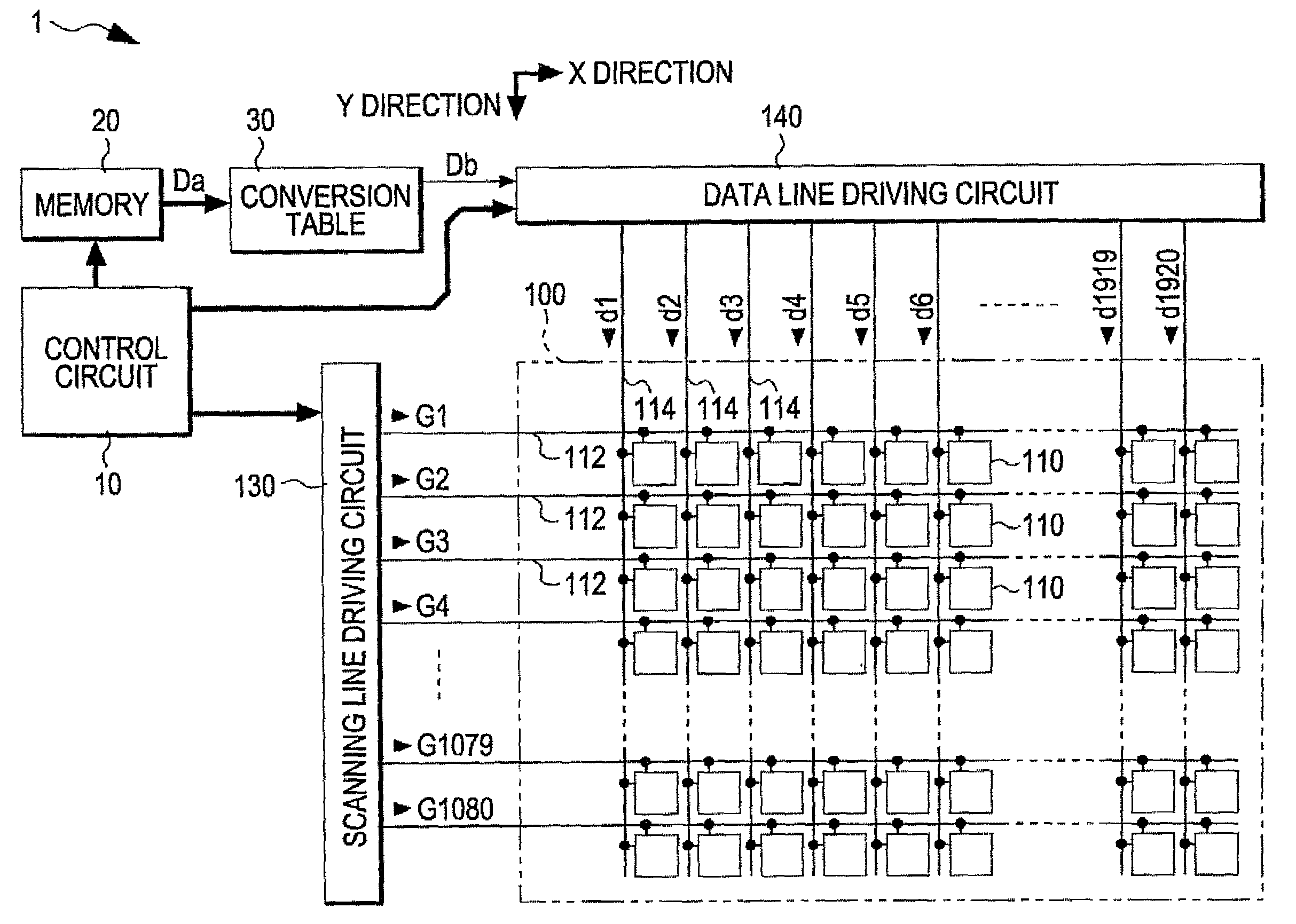
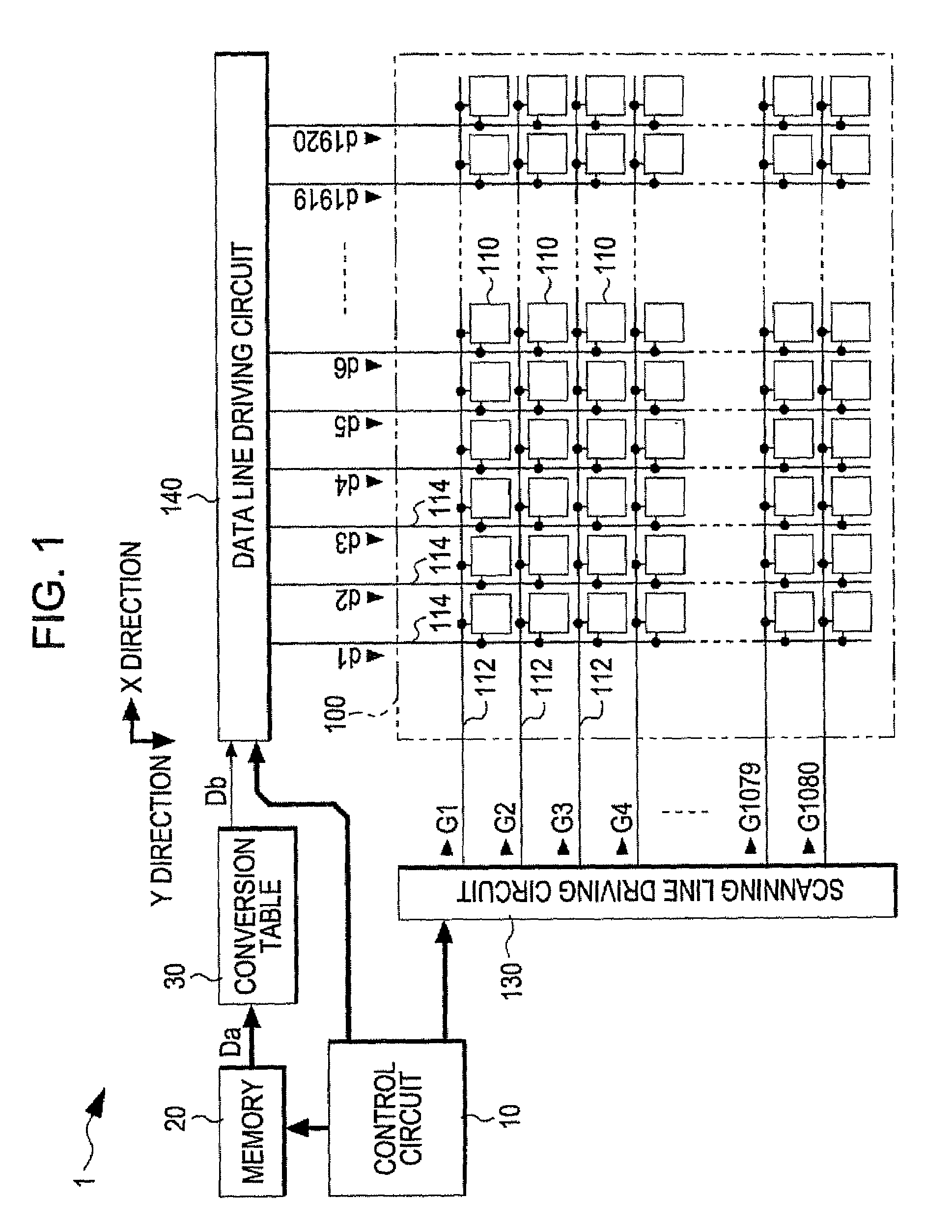
[0037]First, a first embodiment of the invention will be described. FIG. 1 is a block diagram that shows the overall configuration of an electro-optical device 1 according to the first embodiment. As shown in the drawing, the electro-optical device 1 roughly includes a control circuit 10, a memory 20, a conversion table 30, a display circuit 100, a scanning line driving circuit 130 and a data line driving circuit 140. The control circuit 10 controls portions of the electro-optical device 1, as will be described later. The display circuit 100 includes pixels that are arranged in a matrix. Specifically, the display circuit 100 includes 1080 scanning lines (writing scanning lines) 112 that extend in a horizontal X direction in the drawing and 1920 data lines 114 that are electrically insulated from the scanning lines 112 and that extend in a vertical Y direction in the drawing. Then, the pixels 110 are provided at portions corresponding to intersections of the scanning lines 112 and th...

first application

and Modification of First Embodiment

[0097]In the above described first embodiment, the enable signal Enb1 is supplied to one of input ends of each odd-numbered AND circuit 134 and the enable signal Enb2 is supplied to one of input ends of each even-numbered AND circuit 134. The reason why the above configuration is employed is as follows. That is, by sequentially shifting the start pulse Dy using the shift register 132, the odd-numbered and even-numbered shift signals become an H level pulse at the same time. The pulse is taken out by the enable signal Enb1 in each odd-numbered line and is taken out by the enable signal Enb2 in each even-numbered line through logical operation to thereby make the scanning signal be not at an H level overlappingly. That is, in the first embodiment, two shift signals are allowed to overlappingly become an H level, and the shift signals are taken out so as not to overlap between in the odd-numbered lines and in the even-numbered lines to thereby obtain...

second application

and Modification of First Embodiment

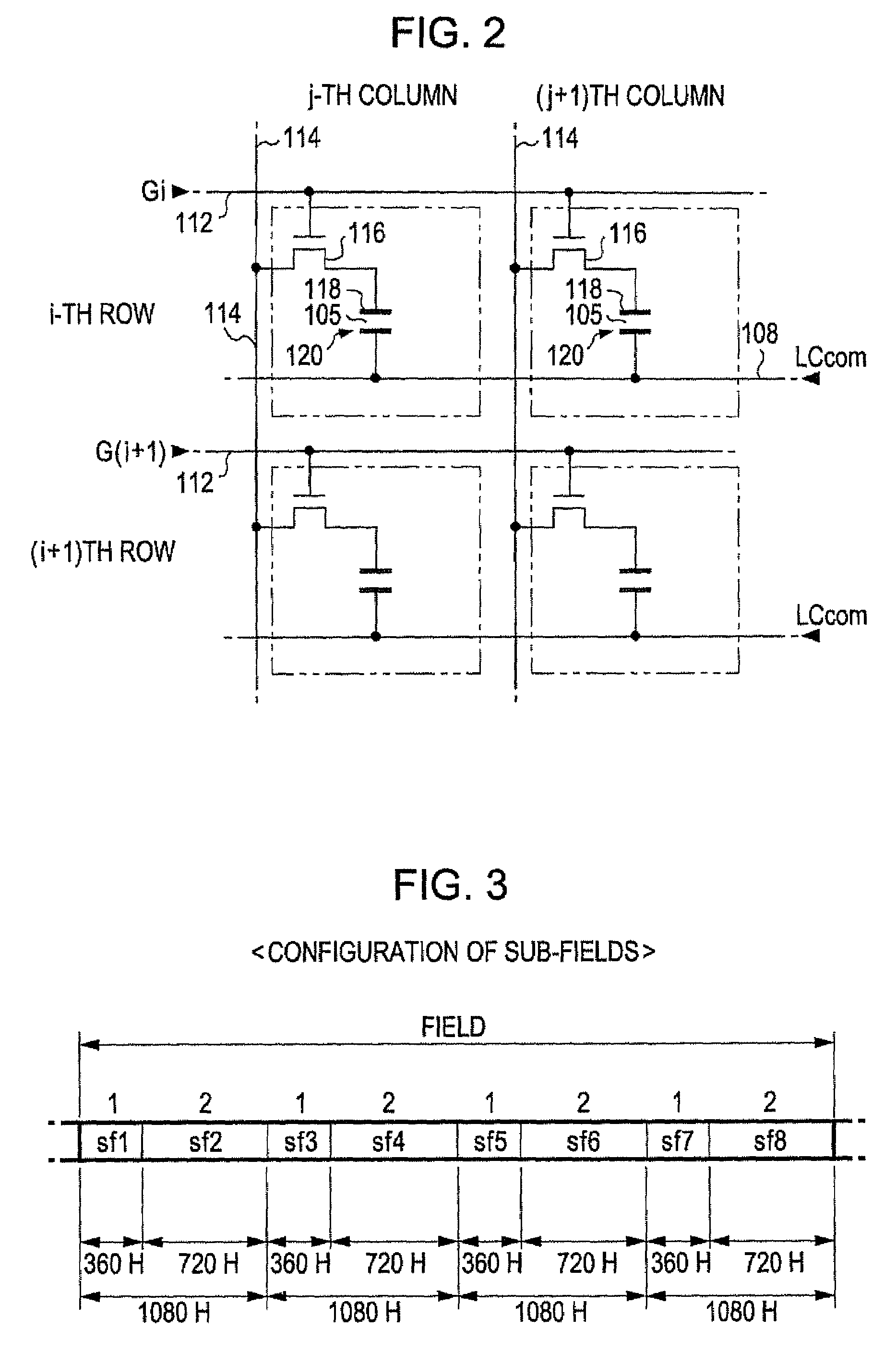
[0099]In the first embodiment, any one of an on voltage or an off voltage is applied to the liquid crystal elements 120 in each of the sub-fields sf1 to sf8; however, an intermediate (half) voltage may be added in addition to choices of an on voltage and an off voltage. Note that the half voltage, for example, as shown in FIG. 13, is Vg(+), which is an intermediate voltage between the voltage Vw(+) and the voltage vb(+) when positive polarity writing is specified, and is Vg(−), which is an intermediate voltage between the voltage Vw(−) and the voltage Vb(−) when negative polarity writing is specified. In addition, actually, a sub-field to which a half voltage is allocated will be selected in consideration of the actual reflectance ratio characteristics of the liquid crystal element 120 with respect to gray-scale levels.

[0100]In the first embodiment, when the gray-scale level “9” is set, an on voltage is applied in the sub-fields sf2 to sf4 and sf7...


PUM


Abstract

A driving circuit of an electro-optical device includes a scanning line driving circuit and a data line driving circuit. When a writing scanning line is selected, the data line driving circuit supplies a data signal of an on or off voltage allocated to a sub-field corresponding to the selection in terms of a gray scale of the pixel corresponding to the selected one of the writing scanning lines and one of the data lines. Among the plurality of sub-fields, the length of a time period of the shortest sub-field is set shorter than the length of a time period required to select, by the scanning line driving circuit, the plurality of writing scanning lines.

Description

BACKGROUND[0001]1. Technical Field[0002]The present invention relates to a technology for making a display element perform gray scale in such a manner that one field is divided into a plurality of sub-fields and then an on or off voltage is applied to the display element in each of the sub-fields.[0003]2. Related Art[0004]When the gray scale is performed in an electro-optical device that uses display elements, such as liquid crystal elements, as pixels, the following technology has been proposed as a substitute for a voltage modulation method. That is, there has been proposed a technology for performing gray scale in such a manner that one field is divided into a plurality of sub-fields and then an on or off voltage is applied to the pixels (liquid crystal elements) in each sub-field to thereby change the percentage of time during which an on voltage (off voltage) is applied to the pixels in the one field, which is described in JP-A-2003-114661. Moreover, in the above technology, us...

Claims


Application Information

Patent Timeline
Patent Type & Authority Applications(United States)
IPC IPC(8): G09G5/10
CPCG09G3/2022G09G2320/0276G09G3/3677G09G3/3614
Inventor IISAKA, HIDEHITOHOSAKA, HIROYUKI
Owner SEIKO EPSON CORP
Why Eureka
Try Eureka