Fixation plate

a technology of fixing plate and bone, applied in the field of bone fixation plate, can solve the problems of weak stress zone subject to breakage, increased tumor occurrence,

Active Publication Date: 2006-09-21
SECUROS
View PDF38 Cites 33 Cited by
  • Summary
  • Abstract
  • Description
  • Claims
  • Application Information

AI Technical Summary

Benefits of technology

[0006] It is a further object of this invention to provide such a bone fixation plate which is thinner, lightweight, and strong.

Problems solved by technology

Also, there have been reports of an increased tumor occurrences when these fixation plates are used.
In many fixation plates, there is a fairly sharp transition between the wide and narrow sections of the fixation plate resulting in a possible weak stress zone subject to breakage.

Method used


Image

  • Fixation plate
  • Fixation plate
  • Fixation plate

Examples


Embodiment Construction

[0023] Aside from the preferred embodiment or embodiments disclosed below, this invention is capable of other embodiments and of being practiced or being carried out in various ways. Thus, it is to be understood that the invention is not limited in its application to the details of construction and the arrangements of components set forth in the following description or illustrated in the drawings. If only one embodiment is described herein, the claims hereof are not to be limited to that embodiment. Moreover, the claims hereof are not to be read restrictively unless there is clear and convincing evidence manifesting a certain exclusion, restriction, or disclaimer.

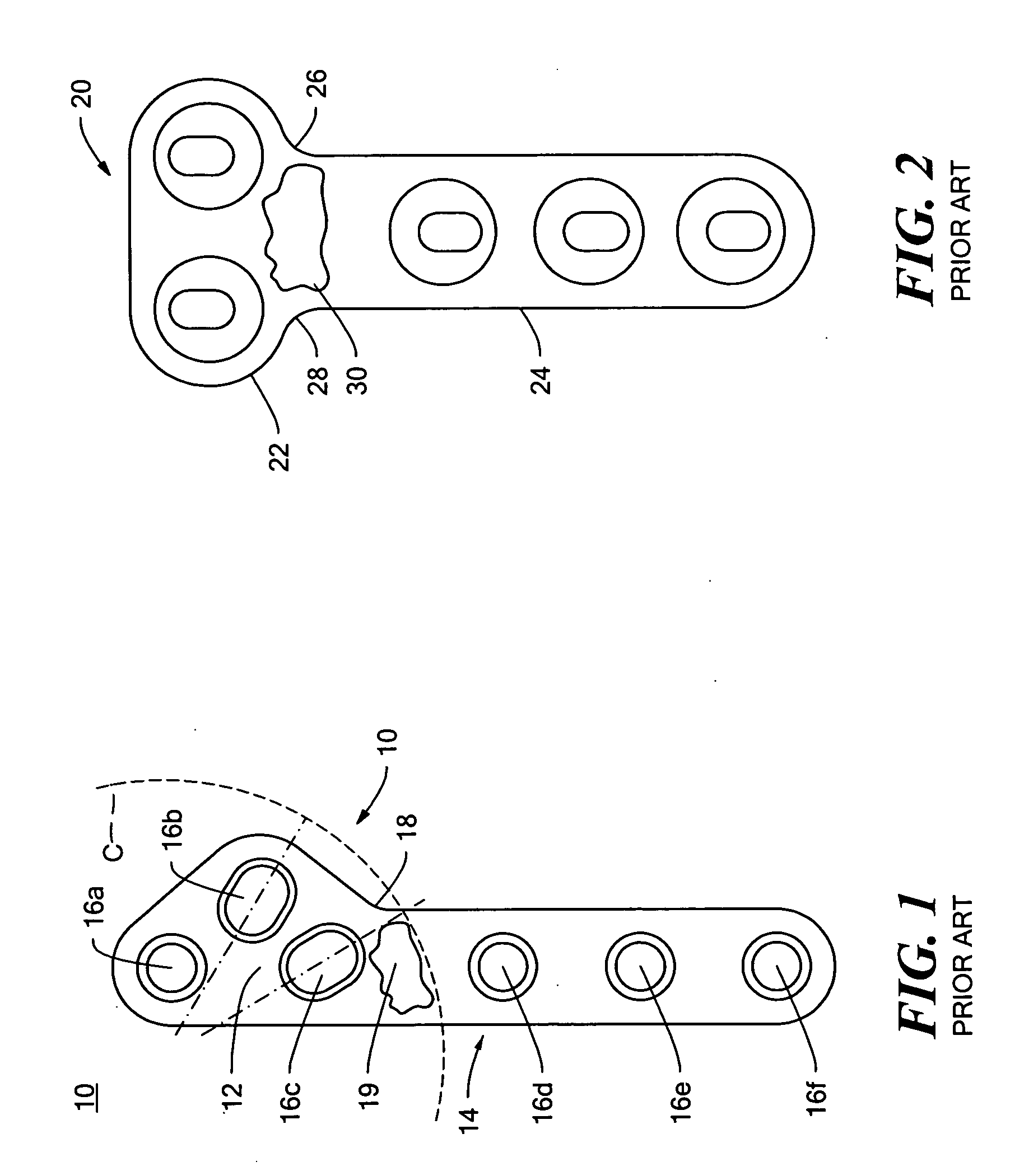
[0024] The tibial osteotomy fixation plate 10, FIG. 1 of patent No. 5,304,180 is shown spanning curvilinear cut C wherein triangular portion 12 is to be attached to the metaphysis and leg portion 14 is to be attached to the tibia using bone screws (not shown) seated in apertures 16a-f. As discussed in the Background secti...


PUM


Abstract

A fixation plate with a base section including apertures for fixation to one bone segment and a leg section extending from the base section and including apertures for fixation to another bone segment. The expanse of the base section tapers gradually to smoothly cojoin with the leg section and the expanse of the leg section continues to taper to a distal rounded end of the leg section.

Description

FIELD OF THE INVENTION [0001] This subject invention relates to a bone fixation plate. BACKGROUND OF THE INVENTION [0002] Bone fixation plates are used in tibial osteotomy and other procedures to secure two bone segments together. In a tibial osteotomy, for example, a curvilinear cut is made in the canine proximal tibia to separate the metaphysis from the proximal tibia. Next, the metaphysis is rotated to level the tibial plateau. Finally, the metaphysis is fixed to the proximal tibia by a fixation plate. See U.S. Pat. No. 5,304,180 incorporated herein by this reference. The fixation plate of this patent includes a broad triangular portion to be fixed to the metaphysis of the tibia and a narrower leg section to be fixed to diaphysis of the tibia. There are three bone screw holes in the triangular portion and three bone screw holes in the leg section. [0003] The fixation plate produced in accordance with this patent, however, is cast from surgical grade stainless steel and thus is re...

Claims


Application Information

Patent Timeline
Patent Type & Authority Applications(United States)
IPC IPC(8): A61F2/30
CPCA61B17/80
Inventor WOTTON, HAROLD M. III
Owner SECUROS
Why Eureka
Try Eureka