
Shoe Heel Support Device

a technology for supporting devices and shoes, which is applied in the direction of fastenings, shoes, clothing, etc., can solve the problems of narrow stein structure of the heel sinking in between, the heel sinking into the ground being walked upon, and the difficulty of walking on such a surface, so as to reduce the height of the device, improve aesthetics, and leave more of the heel uncovered

Inactive Publication Date: 2011-12-29
NAISMITH BEELEY ILDE
View PDF9 Cites 14 Cited by
  • Summary
  • Abstract
  • Description
  • Claims
  • Application Information

AI Technical Summary

Benefits of technology

[0007]The present invention is directed to a shoe heel support device, which may at least partially overcome at least one of the abovementioned disadvantages, an alternative with some advantage or provide the consumer with a useful or commercial choice.
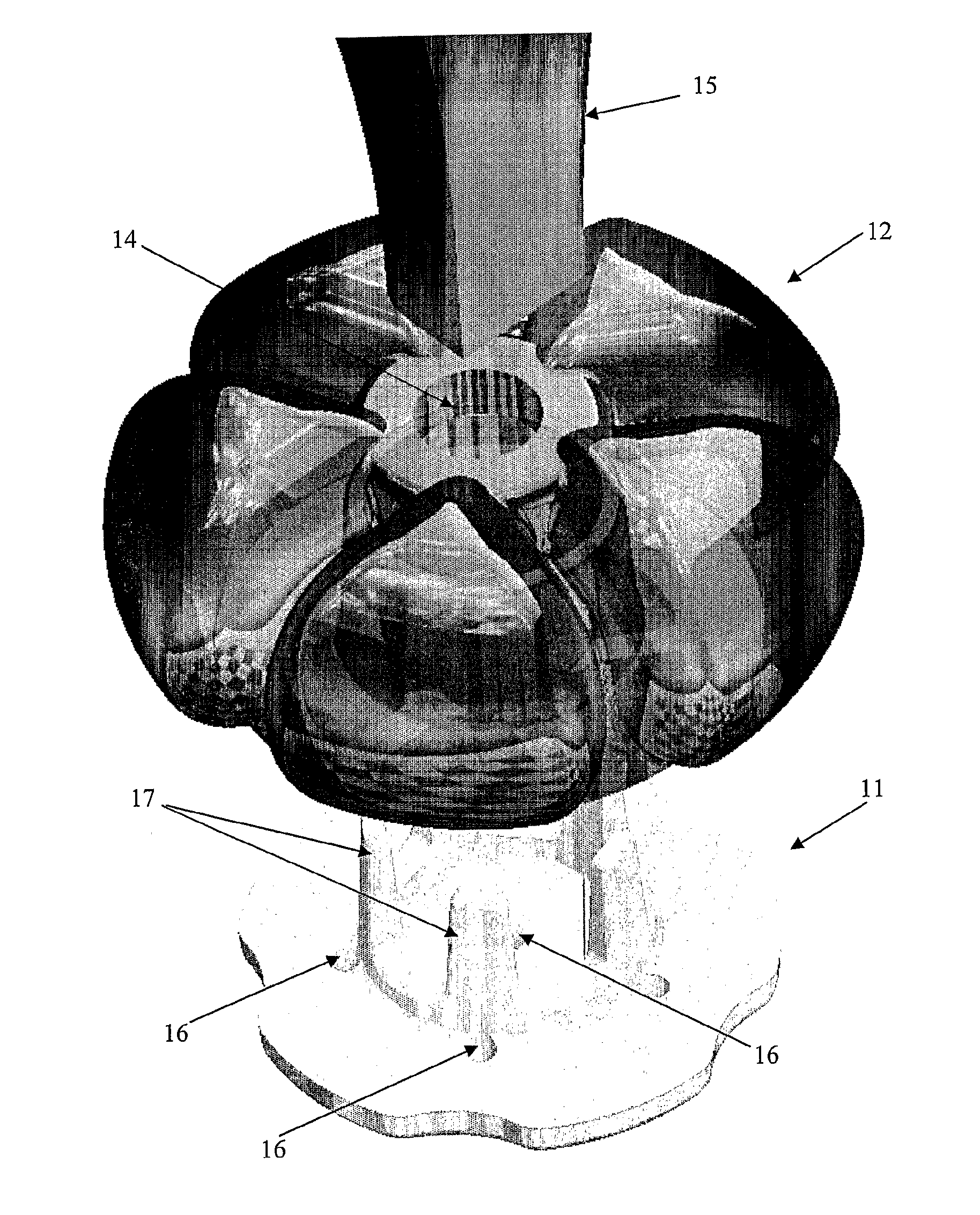
[0010]The base portion is typically configured as a planar member with at least one and normally a number of upright extensions. These extension portions are preferably shaped to engage with the resilient heel engagement portion. Typically the upright portions will both attach and stabilise the heel engagement portion. The upright portions are normally arrayed in a circular configuration about the bore of the device and extend upwardly into but not through the heel engagement portion. These upright portions may provide the device, and more particularly the resilient heel engagement portion with increased stiffness or rigidity.
[0021]If necessary, the device may be provided with more rigid or stiff interconnections between the lobes or beads. This may be used in situations where it is found that the device does not engage with the shoe heel securely enough and may come loose. Of course, increased rigidity may be provided by at least partially connecting the lobes to each other and both adjacent the bore and at other portions between the lobes. If required, additional resilient means may be provided in association with the lobes in order to provide sufficient stiffness or resistance against the resilient deformation.
[0026]Preferably, the device of the preferred embodiment will be configured to provide a gradual increase in the surface area of the device as the device abuts relatively soft ground.
[0028]The device of the present invention is sized for a combination of aesthetics, and not interfering with walking (snowshoe / flipper effect) but still being large enough to function of inhibiting penetration of the heel of the shoe into relatively soft ground.
[0029]Also by using the “outwardly deformed lobes” and not relying on a sleeve / vacuum / friction method to provide the adhesion to the heel, the device reduces the height of the device to a minimum to leave more of the heel uncovered and improving aesthetics but also for keeping the device compact so that it can be carried discreetly in a clutch purse etc.

Problems solved by technology

A problem that may be encountered by a person wearing shoes with such a heel is that the heel may sink into the ground that is being walked upon.
This is a particular problem when the ground is soft, such as sand or grass.
In these instances, it can become difficult for the person to walk upon such a surface, as the heel must often be pulled out of the ground with each step.
A similar problem can be encountered when the ground is relatively unstable, such as when walking on a gravel road or path.
In such an event, the narrow stein structure of the heel can sink in between rocks or pebbles that make up the ground.
This may lead to general instability for the person walking thereon, thereby increasing the possibility of injury by, for example, falling and spraining or twisting an ankle.
In addition, in such circumstances, there is also the capacity for causing damage to the shoe, in particular the heel.
The likelihood of damage to the shoe is greater for those shoes that are manufactured from delicate materials, such as suede or fine fabrics.
Unfortunately, it is often the case that such shoes are most often the most expensive to buy and their subsequent repair or replacement may come at significant expense to their owner.
Similar safety and shoe maintenance problems can also be encountered when high heeled shoes are worn whilst walking upon a surface that has numerous or significant gaps, for example, upon planks of a decking surface.

Method used


Image

  • Shoe Heel Support Device
  • Shoe Heel Support Device
  • Shoe Heel Support Device

Examples


Embodiment Construction

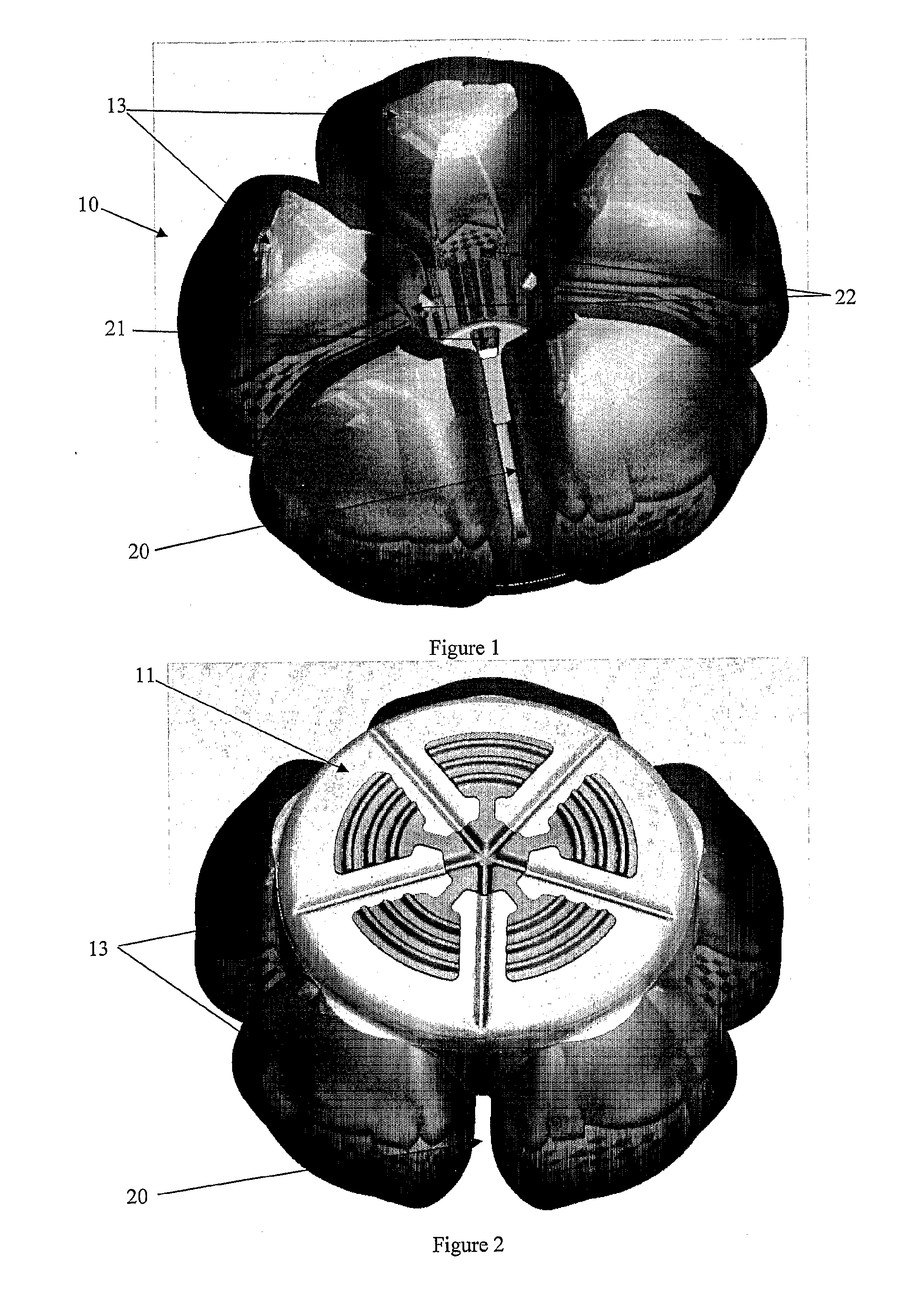
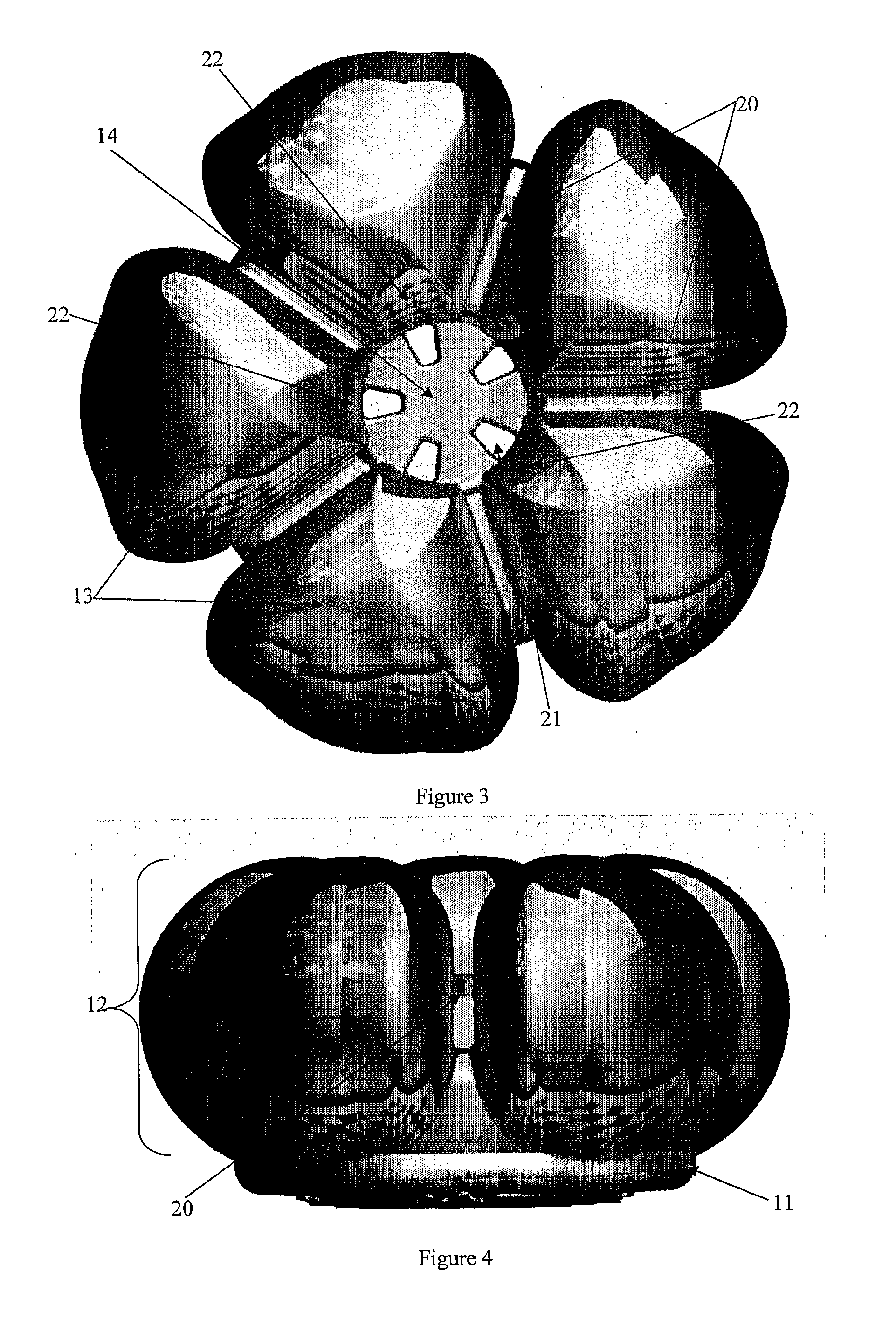
[0043]According to a particularly preferred embodiment, a shoe heel support device is provided. In the illustrated embodiments, the same reference numbers are used to refer to the same component parts in FIGS. 1-11, but the reference numbers are not in conformity in FIG. 12.

[0044]Referring to the drawings, particularly FIGS. 1-4, the embodiment of the shoe heel support device has a substantially unitary configuration when assembled but has a pair of components as illustrated in FIG. 5.

[0045]The shoe heel support 10 illustrated the figures includes a ground contacting base 11 and a resilient shoe heel engagement portion 12 attached to the ground contacting base 11. The resilient shoe heel engagement portion of the illustrated embodiment includes five lobe portions 13 each having an inner surface which together define a bore 14 for receiving a shoe heel 15 therein in an interference fit 19 as illustrated in FIG. 7.

[0046]As illustrated in the Figures, the device 10 has a generally toro...


PUM


Abstract

A shoe heel support device including a ground contacting base portion and a resilient shoe heel engagement portion attached to the ground contacting base portion, the resilient shoe heel engagement portion including at least three lobe portions each having an inner surface together defining a bore for receiving a shoe heel therein, the dimension of the bore smaller than the cross-sectional dimension of the shoe heel.

Description

FIELD OF THE INVENTION[0001]The present invention relates to a support device for a shoe heel to provide as supporting platform for the heel of the shoe, such as providing support for a stemmed or high heel, particularly useful for preventing or inhibiting the deal from sinking into a surface when issue is being worn will stopBACKGROUND ART[0002]Devices similar to that of the present invention are available. One such device is described in International Patent to Publication No. WO 2007 / 124534 which also contains a useful description of the prior art to date. A section of the “Background of the Invention” portion of that document is as follows verbatim:[0003]“It is well known that there is a large number of different types of footwear, including shoes that cater for different functions and fashions. Women's shoes, in particular, are often equipped with a raised or high heel. In many instances, the design of the heel is such that the heel is relatively narrow in width, with the heel ...

Claims


Application Information

Patent Timeline
IPC IPC(8): A43B13/14
CPCA43B1/0018A43B13/00A43C15/04A43B3/166
Inventor NAISMITH-BEELEY, MARK
Owner NAISMITH BEELEY ILDE
Learn More