Lumbar spine pedicle screw guide

a pedicle screw and guide technology, applied in the field of pedicle screw instruments, can solve the problems of low success rate and accuracy, high accuracy, and high equipment requirements, and achieve the effect of reducing the deviation of the bas

Inactive Publication Date: 2017-11-14
KING SAUD UNIVERSITY
View PDF14 Cites 17 Cited by
  • Summary
  • Abstract
  • Description
  • Claims
  • Application Information

AI Technical Summary

Benefits of technology

[0007]The lumbar spine pedicle screw guide includes a base for covering at least one exposed spinous process of the vertebra; a midline stabilization system within an interior portion of the base for reducing deviation of the base from a central alignment along the first axis of the midline of the vertebra; a sliding top disposed over an exterior surface of the base, the sliding top being configured for movement over a length of the base along the first axis; at least one calibration arm having a straight portion and a curved end, the at least one calibration arm being movably connected to the sliding top and configured for movement along a second axis perpendicular to the first axis; and a pedicle access unit mounted on each of the at least one calibration arm and capable of being secured at different locations thereon, the pedicle access unit having a hollow interior for receiving medical instruments therethrough. The sliding top can be adjusted to align the at least one calibration arm with a target vertebra. The medical instruments and a screw can be accurately guided through the pedicle access unit into a pedicle of the target vertebra.

Problems solved by technology

Such techniques, however, often require complex or expensive equipment in order to achieve a high rate of accuracy (e.g., greater than 90%).
Consequently, free-hand techniques, having lower success rates and accuracy (e.g., 68%-80%), are the most commonly used techniques.
Pedicle guides used with free-hand techniques can sometimes incorporate parts that must be inserted under the bone, which is not recommended because of the risks in neurologic injury and not recommended for patients with spinal canal narrowing (i.e., stenosis).
Additionally, such pedicle guides do not facilitate procedures on two pedicles of the same vertebra at the same device position, thereby resulting in increased x-ray usage and potential variability in pedicle screw placement.
Such pedicle guides also fail to address instrumentation of multiple vertebrae, despite the fact that spinal fusion typically requires instrumentation of two or more adjacent vertebrae.

Method used


Image

  • Lumbar spine pedicle screw guide
  • Lumbar spine pedicle screw guide
  • Lumbar spine pedicle screw guide

Examples


Embodiment Construction

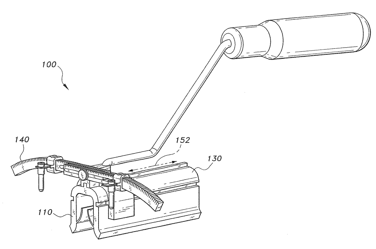
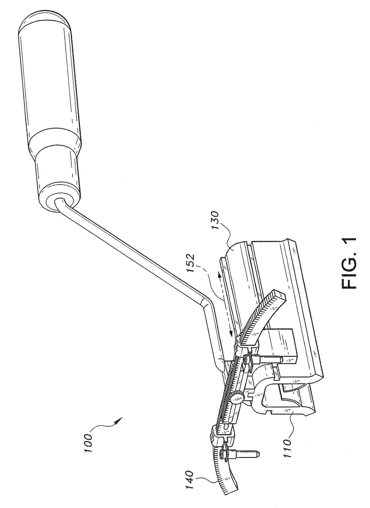
[0020]FIG. 1 illustrates a lumbar spine pedicle screw guide 100 in accordance with the present invention. The lumbar spine pedicle screw guide 100 generally includes a base 110, a sliding top 130, and at least one calibration arm 140. The base 110 is configured to cover at least one exposed spinous process of the lumbar vertebra. Exposure of spinous processes is typically necessary when performing various types of surgical procedures, such as pedicle cannulation, on the vertebra. The base 110 is designed to be centered in the midline of the spine when covering the spinous processes.

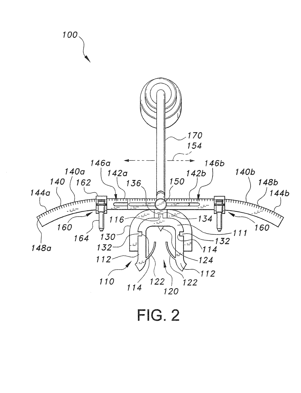
[0021]Referring additionally to FIG. 2, the base 110 has a general U-shaped configuration defined by a top portion 111 and two leg portions 112. The base includes a side track 114 on the outer surface of each leg portion 112. Each side track 114 extends along the entire length of the base 110. Additionally, a key or top protrusion 116 is formed on the outer surface of the top portion 111 and also extends ...


PUM


Abstract

The lumbar spine pedicle screw guide has a base for covering at least one exposed spinous process of the lumbar vertebra and a sliding top disposed over the base and configured for movement over the length of the base along a first axis. At least one calibration arm having a straight portion and a curved portion is movably connected to the sliding top and configured for movement along a second axis perpendicular to the first axis. A pedicle access unit is mounted on each calibration arm and is capable of being secured at different locations thereon. The sliding top can be adjusted to align the calibration arms with a selected vertebra so that medical instruments and a screw can be accurately guided through the pedicle access unit into a pedicle of the selected vertebra.

Description

BACKGROUND OF THE INVENTION[0001]1. Field of the Invention[0002]The present invention relates to pedicle screw instrumentation, and more particularly to a lumbar spine pedicle screw guide for improving the accuracy of pedicle screw insertion and the safety of instrumentation used in pedicles of the lumbar vertebrae.[0003]2. Description of the Related Art[0004]Pedicle screw instrumentation is the main method used to achieve instrumented fusion between the vertebrae in thoracic and lumbar spine regions. The process typically requires insertion of pedicle screws with accuracy and precision in order to avoid injury to the near-by nerve roots and achieve adequate fixation. Various techniques have been developed to improve the accuracy of pedicle screw placement. Such techniques, however, often require complex or expensive equipment in order to achieve a high rate of accuracy (e.g., greater than 90%). Consequently, free-hand techniques, having lower success rates and accuracy (e.g., 68%-8...

Claims


Application Information

Patent Timeline
Patent Type & Authority Patents(United States)
IPC IPC(8): A61B17/88A61B17/70
CPCA61B17/7083A61B17/1757
Inventor AL-HABIB, AMRO FAYEZAL-AHMARI, ABDULRAHMANAMEEN, WADEA
Owner KING SAUD UNIVERSITY
Why Eureka
Try Eureka