[0008]A further refinement of the present invention provides that after the limitation has ceased, the total drive torque is brought in line with the
setpoint drive torque in a manner that is steady and / or that limits the rate of change. Thus, when the limitation is no longer applicable, the shaft torques may be adjusted again by the open-loop and / or closed-
loop control in such a way that their sum corresponds to the setpoint drive torque. To prevent an abrupt change in the total drive torque, which could influence the safety of the motor vehicle, the total drive torque is altered steadily and / or in a manner that limits the rate of change. This means that the deviation of the total drive torque from the setpoint drive torque is reduced steadily and / or with limitation in the rate of change. The change is implemented until the total drive torque corresponds generally to the setpoint drive torque again. In this manner, the driver of the motor vehicle has
sufficient time to adapt himself to the altered operating conditions, and perhaps to adjust the setpoint drive torque. Naturally, in this case, the setpoint drive torque may likewise be adjusted by the driver assistance
system.
[0009]A further development of the present invention provides that, in order to change the total drive torque steadily and / or in a manner that limits the rate of change, at least one of the shaft drive devices is operated in an overload range and / or at an unfavorable
operating point. During normal operation of the motor vehicle, thus, when there is no limitation, the shaft drive devices are to be operated in such a way that there is neither an overload, nor is the shaft drive device operated at an unfavorable
operating point. For instance, the latter may be characterized by high specific fuel consumption and / or high emissions values. On the other hand, if the limitation is present and, because of the limitation of at least one of the shaft torques, the setpoint drive torque cannot be reached, particularly without overloading or unfavorable operating points, then at least one of the shaft drive devices may be operated in the overload range and / or at the unfavorable operating point, in order to allow the total drive torque to change in a manner which is steady and / or limited in the rate of change. For example, in response to the failure of one of the shaft drive devices, a further shaft drive device is operated with a higher output, in doing which, only a short-duration operation is possible without damage to the shaft drive device, and at the same time, the specific fuel consumption is high. During the operation of the shaft drive device in such a manner, the total drive torque is changed steadily and / or in a manner that limits the rate of change, so that the total drive torque is adjusted to a value which permits operation of the shaft drive device in a permanently permissible range. In this manner, the safety of the motor vehicle may be increased considerably by the short-duration operation of the shaft drive device outside of the permanently permissible and / or desired range. Since the shaft drive device is operated in the undesirable range for only a short period, it can suffer no damage.
[0011]In another refinement of the present invention, the total drive torque is changed in such a way that an absolute value of the total drive torque is less than an absolute value of the setpoint drive torque, and / or the total drive torque approaches zero. Thus, during the change of the total drive torque, its absolute value is
not to exceed that of the setpoint drive torque. The altered total drive torque should thus always lie between the original value of the total drive torque or of the setpoint drive torque and a value of zero. In this manner, the total drive torque can not increase or decrease unexpectedly for the driver. It may, therefore, also be provided for the total drive torque to approach zero. For instance, this may be provided in response to an especially serious fault in one of the shaft drive devices, in order to bring the motor vehicle safely to a halt. This means that if the vehicle is in traction mode with positive total drive torque, the total drive torque should be reduced in the direction of zero as soon as a limitation exists, in order to avoid an unintentional acceleration of the vehicle. Conversely, in the case of a negative total drive torque, thus, the motor vehicle is in overrun, the total drive torque should preferably be altered in the direction of zero as soon as the limitation occurs, in order to prevent a sudden deceleration.
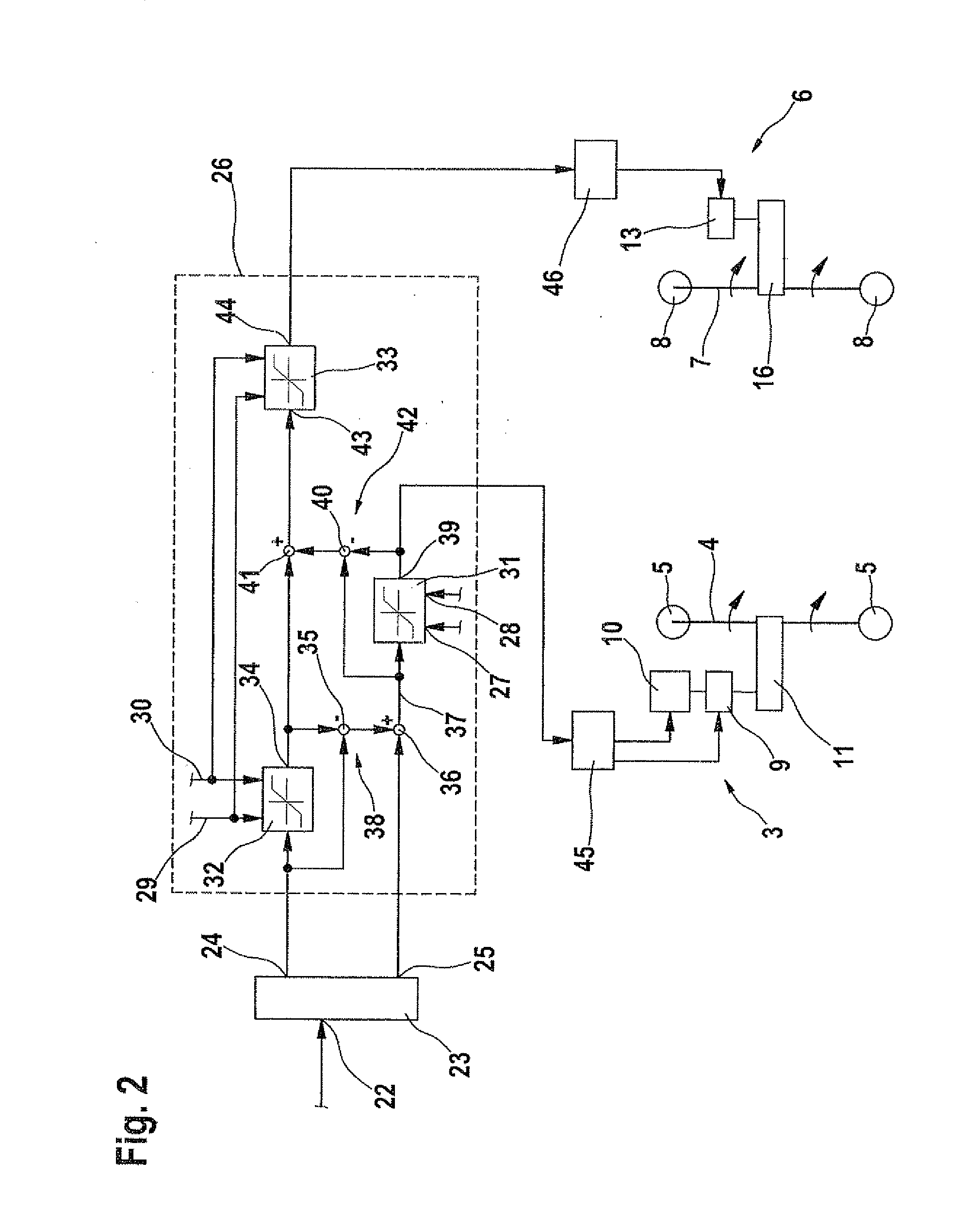
[0012]In a further development of the present invention, the setpoint drive torque is filtered. Thus, the setpoint drive torque does not correspond directly to the input by the driver of the motor vehicle, but rather is only coupled to it. It is provided to filter the input of the driver and / or of the driver assistance
system before the total drive torque of the motor vehicle is adapted to it. This is intended to prevent the total drive torque of the motor vehicle from being able to change too rapidly and / or abruptly.
[0014]Another refinement of the present invention provides for setting the minimum torque and / or
maximum torque as a function of a torque range able to be made available by the shaft drive device and / or a speed regulation of one of the shaft drive devices and / or an emergency operation / fault condition and / or a gear shift in a transmission and / or values of a
vehicle dynamics control. The minimum torque and / or
maximum torque may thus be adapted to the torque range able to be made available by the shaft drive device, or to an optimal torque range of the same. The minimum torque and / or the
maximum torque may also be set based on a speed regulation of one of the shaft drive devices. For instance, the speed regulation may be provided due to a malfunction or an unfavorable operating condition (e.g., overheating). The speed regulation may also be provided in the form of a boost speed regulation in order to distribute the available energy content of the electrical energy store or of the traction battery over several boost procedures. In addition, recognized emergency operation / fault conditions and gear shifts are incorporated into the values of the minimum torque and / or maximum torque. It is also advantageous if the permissible torque range, thus, the range bounded by the minimum torque and / or maximum torque, is set as a function of values of a
vehicle dynamics control. This may be provided in order to increase the stability of the motor vehicle.

