
Lamp structure with a function of candlestick

Inactive Publication Date: 2006-09-28
LIPAN INDAL
View PDF10 Cites 26 Cited by
  • Summary
  • Abstract
  • Description
  • Claims
  • Application Information

AI Technical Summary

Benefits of technology

[0007] The primary object of the present invention is to provide a lamp structure with a function of candlestick, which comprises primarily a lamp seat and a light source (light bulb) installed on the seat, with a transparent shade covered on a periphery at a top of the light source. A liquid containing transparent or reflective floating objects or other dynamic devices with changeable colors is filled in the transparent shade. A candlestick of a dish shape is at a top of the transparent shade for holding a candle. Light is projected into the transparent shade by the light source, and in the same time a heat generated by the light source is used to heat up the liquid in the transparent shade, creating a visual effect of dynamic change to the floating objects, thereby increasing the interest of application.
[0008] Another object of the present invention is to install at the same time a battery chamber for providing a DC power, and an adapter device for providing an AC power, so as to apply to a conventional AC, DC power at the same time, thereby increasing the convenience in application.

Problems solved by technology

However, as time advances, candles of insufficient brightness have been gradually replaced by light bulbs, and turned into a tool representing romance.
However, the design of the aforementioned lamp structure is only for a single light source (light bulb).
Therefore, the lamp structure cannot be used in a circumstance without a power source, which is one of the limitations in application.
In addition, light generated from a light bulb source does not easily replace that from a conventional candle for creating a romantic mood.

Method used


Image

  • Lamp structure with a function of candlestick
  • Lamp structure with a function of candlestick
  • Lamp structure with a function of candlestick

Examples


Embodiment Construction

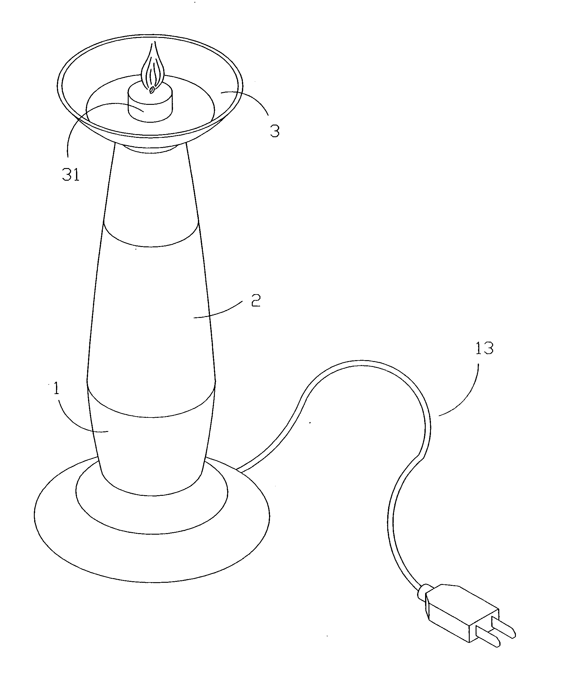
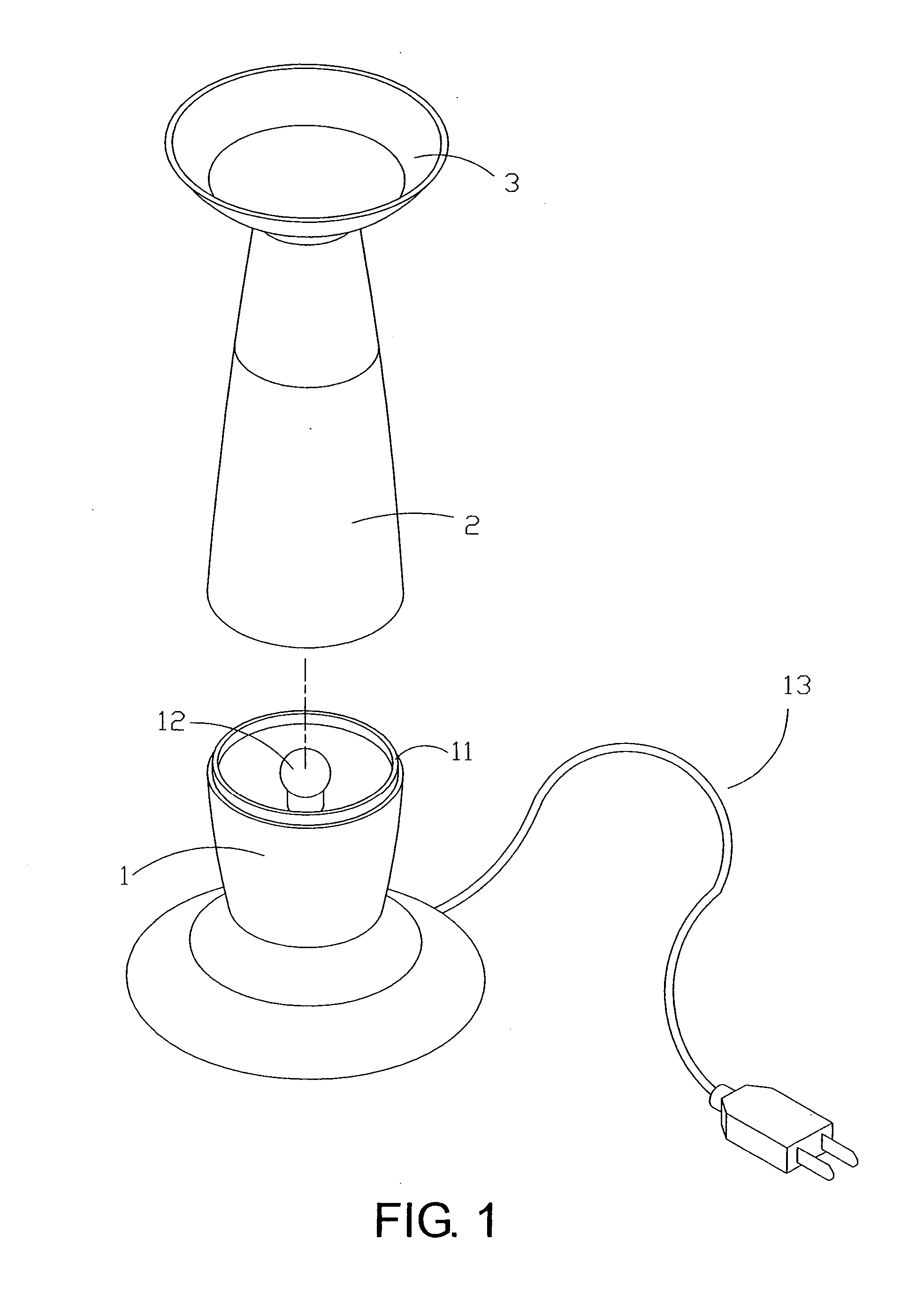
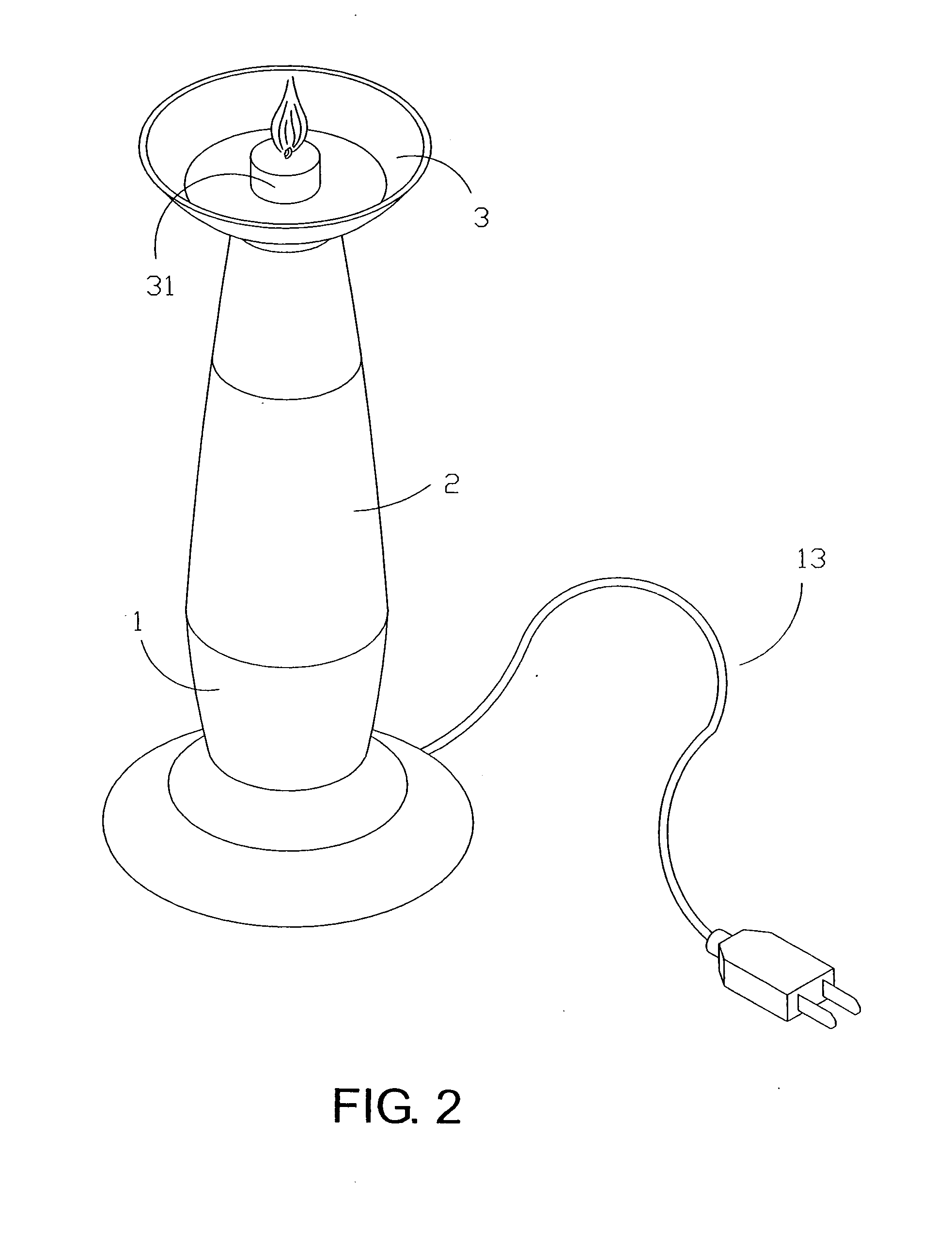
[0017] Referring to FIG. 1 and FIG. 2, the present invention comprises primarily a lamp seat 1, a transparent shade 2, and a candlestick 3, wherein a light source 12 (light bulb) is located at a top side of the lamp seat 1, and a ring of flange 11 is located at a periphery of the light source 12. Both an AC adapter device connected with a power cord 13 and a battery chamber for holding batteries for providing a DC power source are located in the lamp seat 1, so as to provide the necessary AC, DC power sources for the light source 12. The transparent shade 2 is made of a (colored or colorless) transparent material 10 and is a hollow structure with an opening at one end. A ring of groove corresponding to the ring of flange 11 of the lamp seat 11 is located at a periphery of the opening of the transparent shade 2, thus enabling the formation of a sealing by covering the transparent shape 2 on the top of the lamp seat 1. The candlestick 3 is a dish shape body located at a top of the tra...


PUM


Abstract

A lamp structure with a function of candlestick primarily includes a lamp seat, a light source located at a top of the lamp seat, and both a battery chamber provides both a DC power source and an AC power source, enabling the provision of power source to the light source through a conventional AC, DC power source. A liquid containing transparent or reflective floating objects is filled in the transparent shade which is covered on a periphery at a top of the light source. A candlestick in a dish shape is located at a top of the transparent shade, for holding a candle. A visual effect of dynamic change is created to the floating objects by a projection of light into the transparent shade from the light source, and by heating up the liquid in the transparent shade from the light source, thereby increasing the interest in application.

Description

BACKGROUND OF THE INVENTION [0001] (a) Field of the Invention [0002] The present invention relates to a lamp structure with a function of candlestick, and more particularly to a lamp structure also having a candle as an auxiliary light source. [0003] (b) Description of the Prior Art [0004] In old days, a candle is used conventionally as lightening equipment for a primary light source. However, as time advances, candles of insufficient brightness have been gradually replaced by light bulbs, and turned into a tool representing romance. In addition, candles can also be used as an auxiliary light source in a circumstance without a power source. [0005] For a conventional lamp structure, although there are different structural designs according to the variation of structure of the light bulbs (light source), most of the structures basically consist of a casing with a lamp seat for holding related wires (and circuit boards), along with a transparent shade which can be assembled with the la...

Claims


Application Information

Patent Timeline
IPC IPC(8): F21V33/00F21V35/00
CPCF21S10/002F21S19/00F21V35/00G09F13/24
Inventor LEE, KEVIN
Owner LIPAN INDAL
Learn More