Unlock instant, AI-driven research and patent intelligence for your innovation.

High torsional force structure of ratchet device

Active Publication Date: 2006-10-05
LIU LIN LANG
View PDF11 Cites 2 Cited by
  • Summary
  • Abstract
  • Description
  • Claims
  • Application Information

AI Technical Summary

Benefits of technology

[0009] It is the primary object of the present invention to provide a torsional force structure of a ratchet device which includes a body having a head portion at an end of said body, said body having a space which is composed of a first recess and a second recess, said space being constituted by a first cycle and a second cycle, a horizontal center line of said first cycle having a distance from a horizontal center line of said second cycle, said first cycle intersecting said second cycle at two points which are located between said horizontal center lines of said and said second cycles, both sides of said first and second cycles being connected by a tangent which forms an acute angular region between an inner wall of said space socket member, a socket member fitted in said first recess and having a plurality of teeth, a ratchet member fitted in said recess, said ratchet member being a crescent block having an outer side and an inner side, said outer side ratchet member having a plurality of cavities for positioning of a triggered rod, said inner side of side ratchet member having a plurality of teeth engageable with said teeth of said socket member, said ratchet member being provided at two ends thereof with two wedge portions configured to be fitted in said angular region between said inner wall of said space and said socket member, an elastic urging means mounted in said space pushing said ratchet member against said socket member thereby engaging said ratchet with said socket member, said triggering rod being engaged with a top face of said ratchet member for moving said ratchet member, whereby when said triggering rod is first adjusted to move said ratchet member to make one of said wedge portions of said ratchet member fit in said angular region and the said socket member is rotated, said wedge portion of said ratchet member will be forced to be tightly fitted in said angular region thereby enabling said socket member to provide a positive rotating force.

Problems solved by technology

In worse case, this drawback is very significant in small ratchet wrenches.

Method used


Image

  • High torsional force structure of ratchet device
  • High torsional force structure of ratchet device
  • High torsional force structure of ratchet device

Examples


Embodiment Construction

[0019] The following descriptions are of exemplary embodiments only, and are not intended to limit the scope, applicability or configuration of the invention in any way. Rather, the following description provides a convenient illustration for implementing exemplary embodiments of the invention. Various changes to the described embodiments may be made in the function and arrangement of the elements described without departing from the scope of the invention as set forth in the appended claims.

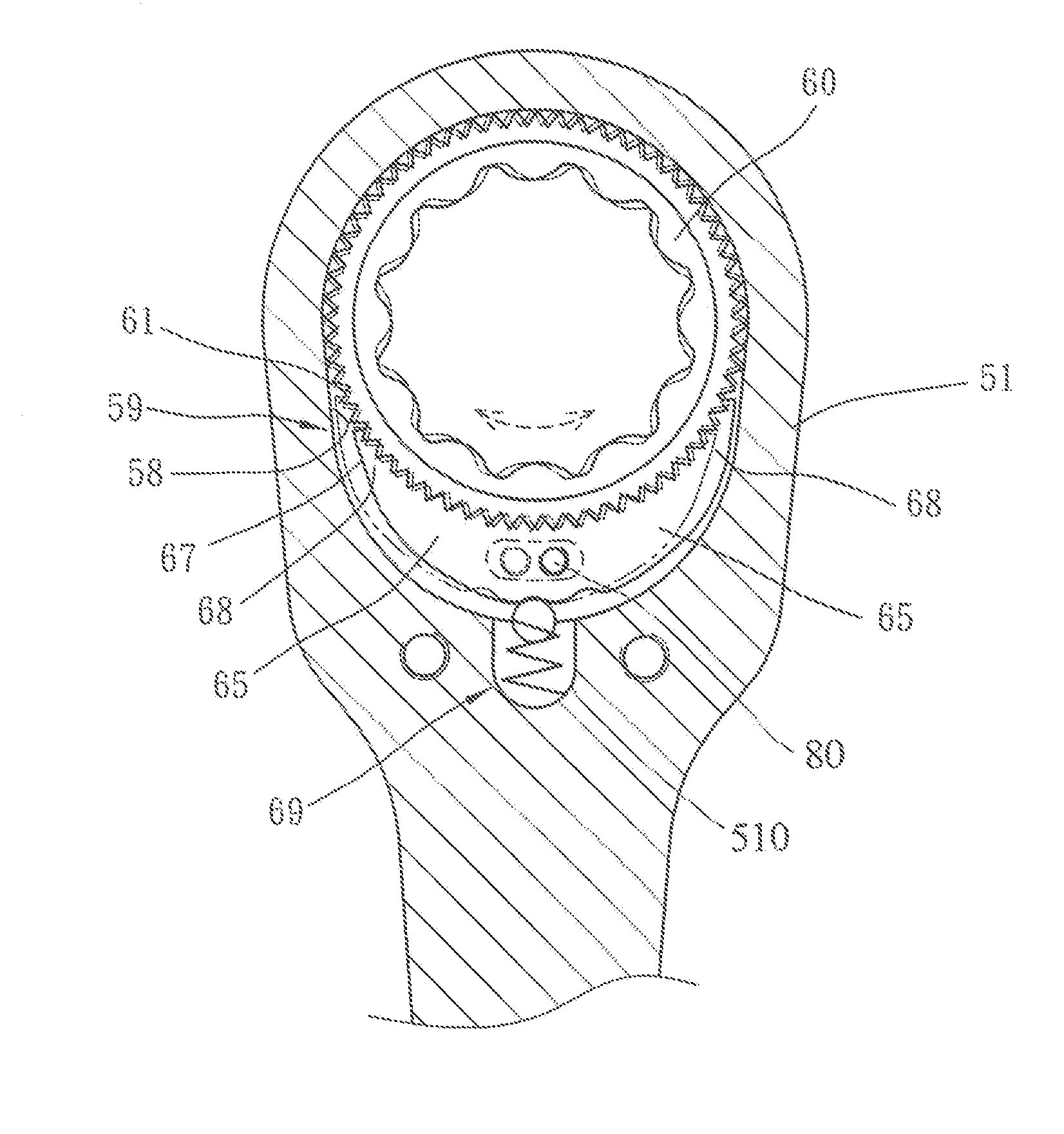
[0020] Referring to FIG. 3, the ratchet device 50 according to the present invention comprises a head portion 51, a socket member 60 and a ratchet member 65. The head portion 51 is formed with a space 52 which is composed of a first recess 53 for receiving the socket member 60 and a second recess 54 for receiving the ratchet member 65. The socket member 60 is provided with a plurality of teeth 61 engageable with teeth 66 of the ratchet member 65.

[0021] As shown in FIGS. 3, 4 and 5, the space 5...


PUM


Abstract

A torsional force structure of a ratchet device which includes a body having a head portion at an end of the body. The head portion has a space which is composed of a first recess and a second recess. A socket member is fitted in the first recess and having a plurality of teeth. A ratchet member is fitted in the second recess and provided at two ends thereof with two wedge portions configured to be fitted in an angular region between the inner wall of the space and the socket member. When the triggering rod is first adjusted to move the ratchet member to make one of the wedge portions of the ratchet member fit in the angular region and the the socket member is rotated, the wedge portion of the ratchet member will be forced to be tightly fitted in the angular region thereby enabling the socket member to provide a positive rotating force.

Description

CROSS-REFERENCE [0001] This application is a continuation-in-part of the co-pending patent application Ser. No. 10 / 647,175, filed Aug. 25, 2003.BACKGROUND OF THE INVENTION [0002] (a) Field of the Invention [0003] The present invention relates to an improvement in the torsional structure of a ratchet device. [0004] (b) Brief Description of the Prior Art [0005] Referring to FIGS. 1 and 2, the prior art ratchet device 10 generally includes a body 11 having a cavity formed with a first recess 12 and a second recess for receiving a socket member 20 and a second recess 15 for receiving a ratchet member 25. A spring 28 is mounted in the body 11 for pushing the ratchet member 25 against the socket member 20 thereby engaging the teeth 26 of the ratchet member 25 with the teeth 21 of the socket member 20. [0006] When the ratchet member 25 is moved to one side to engage the inner wall of the second recess 15, there will be a displacement between the teeth 26 of the ratchet member 25 and the te...

Claims


Application Information

Patent Timeline
IPC IPC(8): B25B13/46
CPCB25B13/463
Inventor LIU, LIN-LANG
Owner LIU LIN LANG