Motion control apparatus

a technology of motion control and actuator, which is applied in the direction of track-braking member co-operation, manufacturing tools, transportation and packaging, etc., can solve the problems of linearly moving load stopping, undesirable forces on piston components of one piece piston assemblies,

Active Publication Date: 2005-08-25
NEXEN GROUP INC
View PDF9 Cites 35 Cited by
  • Summary
  • Abstract
  • Description
  • Claims
  • Application Information

AI Technical Summary

Benefits of technology

[0006] The present invention solves these needs and other problems in the field of linear motion brakes by providing, in the preferred form, an apparatus including a wedge moveable along a first axis. The wedge has a wedge surface arranged nonparallel to the first axis. An actuator is moveable along a second axis perpendicular to the first axis. The actuator has a wedge engaging surface that engages with th...

Problems solved by technology

However, problems have been encountered in stopping linearly moving loads especially in the event of a power outage.
This problem is also enhanced in linear motion de...

Method used


Image

  • Motion control apparatus
  • Motion control apparatus
  • Motion control apparatus

Examples


Embodiment Construction

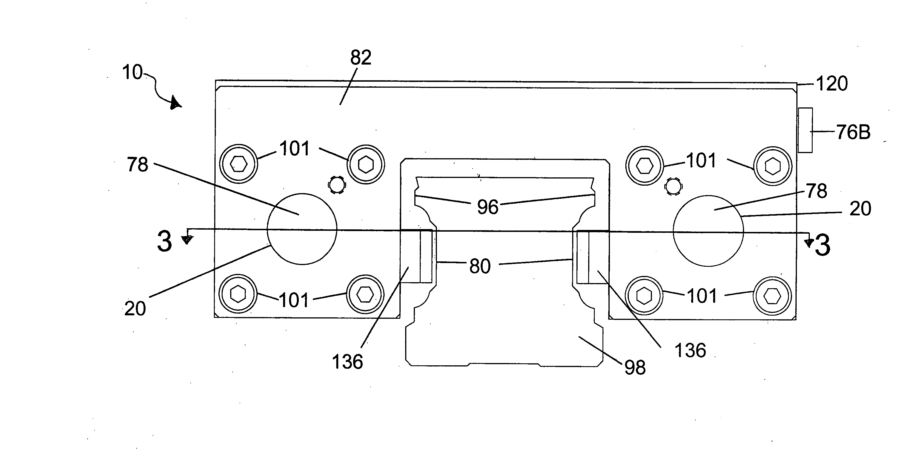
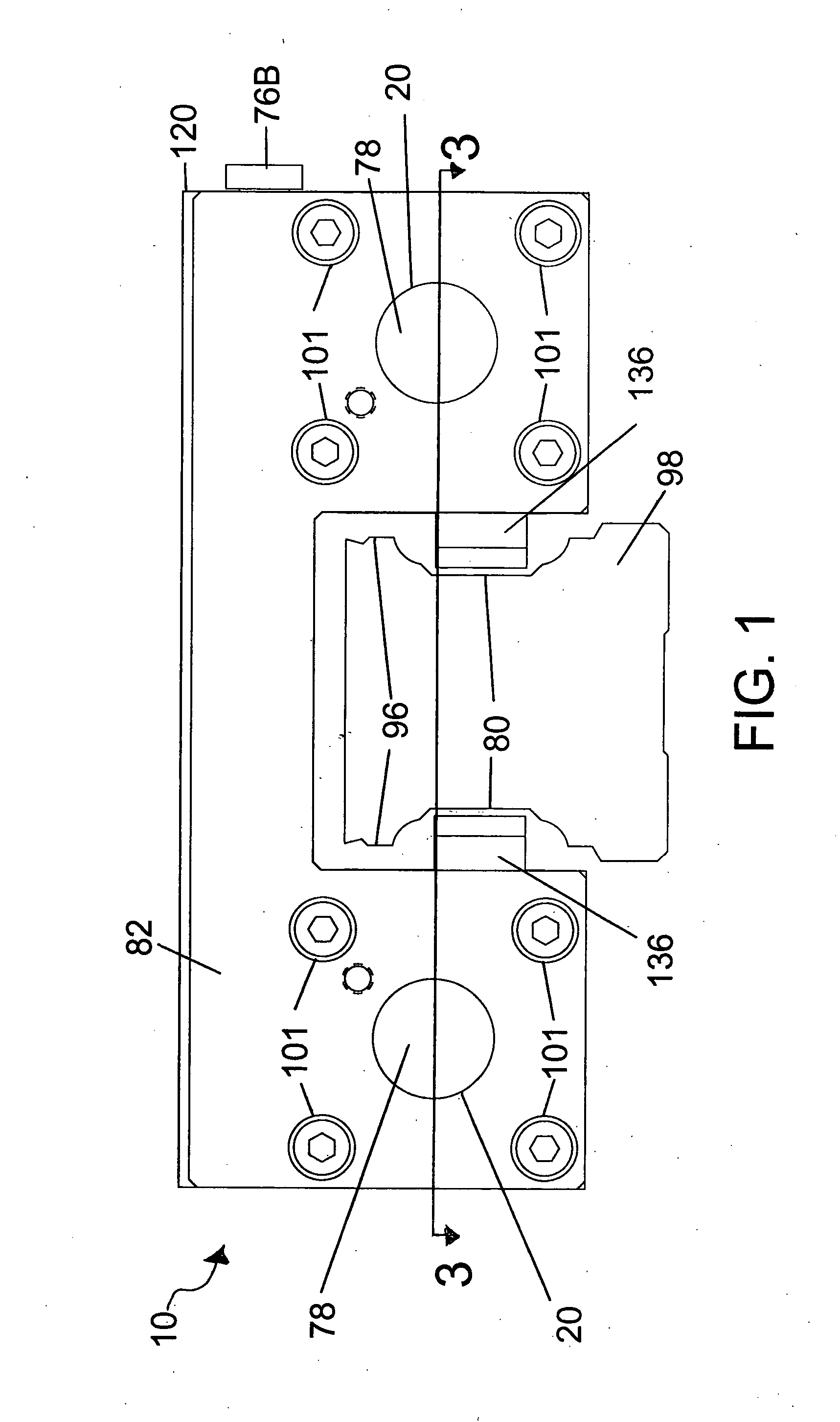
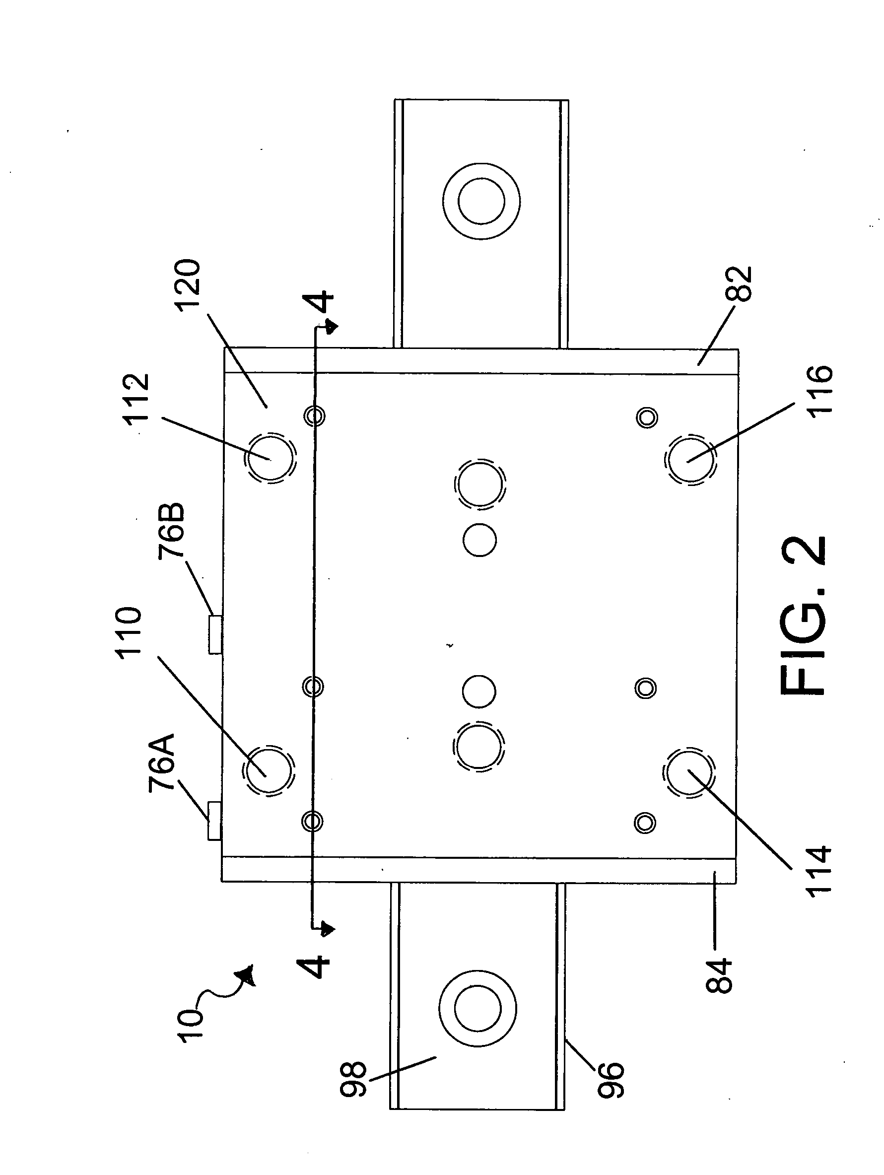
[0029] An apparatus for controlling motion shown in the most preferred form as a brake for stopping linearly moving loads according to the preferred teachings of the present invention is shown in the drawings and generally designated 10. Suitable provisions are provided to house the mechanisms of the brake 10. According to the preferred teachings of the present invention, the brake 10 generally includes a housing 120. Those skilled in the art will recognize that the housing 120 may be constructed from any suitable material able to maintain dimensional stability under the forces and stresses of braking. In one example embodiment according to the preferred teachings of the present invention, the housing 120 is machined from an aluminum extrusion for strength and for reduced weight.

[0030] Housing 120 has two braking actuators 70 that work in concert to provide a braking action on rail 98. Those skilled in the art will recognize that a single one of the two actuators 70 may be used wit...


PUM


Abstract

A brake (10) having application for a linear or rotational motion device includes a housing (120) in which a first piston (140), a wedge (142) and a second piston (144) cooperate to engage a friction facing (136) through a plurality of rollers (152, 154, 156, 158). The three part piston assembly (148) allows a braking action and prevents torsional forces that are non-axial to the axis of the first piston (140) and second piston (144). The pistons (140, 144) are biased by compression springs (176) and may be actuated by a fluid.

Description

BACKGROUND [0001] The present invention generally relates to motion control apparatus and in particular brakes. Specifically, the present invention relates to brakes suitable for use with a track to brake motion such as linear motion, and more specifically relates to linear motion brakes that have improved piston life and that are adjustable. [0002] The popularity of linear motion devices in the machine tool, semiconductor, and medical industries has been increasing as the result of their ability to move a load in a linear movement direction to a position with extreme accuracy and at very high speeds. However, problems have been encountered in stopping linearly moving loads especially in the event of a power outage. Specifically, as movement and positioning of the load is dependent upon current being supplied to the linear motor, loads carried by linear motion devices will move under gravitational and / or inertia forces in the event that current is interrupted to the linear motor suc...

Claims


Application Information

Patent Timeline
IPC IPC(8): B23Q1/28F16D63/00F16D65/14
CPCF16D63/008F16D65/567F16D2125/66F16D2121/12F16D2121/02
Inventor MAHER, JEFFREY M.
Owner NEXEN GROUP INC
Why Eureka
Try Eureka