
System and method for bone fixation

a technology of bone fixation and system, applied in the field of bone fixation system and method, can solve the problems of generating a bending movement at the projecting anchor head, needing posterior procedures, and limited performance, and achieves the effect of reducing the amount of bone material removed, reducing the size of the proximate end of the shank, and improving the holding power of the cable anchor

Inactive Publication Date: 2006-08-15
PIONEER SURGICAL TECH INC
View PDF23 Cites 36 Cited by
  • Summary
  • Abstract
  • Description
  • Claims
  • Application Information

AI Technical Summary

Benefits of technology

"The present invention provides a system and method for maintaining the positions of bones relative to each other during spinal column procedures. The system includes a cable anchoring apparatus in the form of a screw member with an elongated shank that is threaded for substantially its entire length. The screw has an internal driver surface so that the size of its proximate end can be minimized. The screw is fully sunk into the bone, and a flexible cable is attached to it to anchor it to another anchored cable. The cables are attached to the bones so that they can be approximated in fixed position relative to each other. The cable anchoring system can be used in spinal decompression procedures and lateral spinal stabilization. It minimizes interference with surrounding viscera and provides a large bearing surface along its length to minimize points of stress concentration and potential for wear."

Problems solved by technology

However, one significant limitation with these applications is the need for posterior procedures, particularly where anterior procedures would be preferable, but whose performance is limited by the space required of current cable anchors in the body cavity.
Another problem is the toggling effect projecting anchors can create with tensioned cables extending transverse thereto and thus generating a bending movement at the projecting anchor head.

Method used


Image

  • System and method for bone fixation
  • System and method for bone fixation
  • System and method for bone fixation

Examples


Embodiment Construction

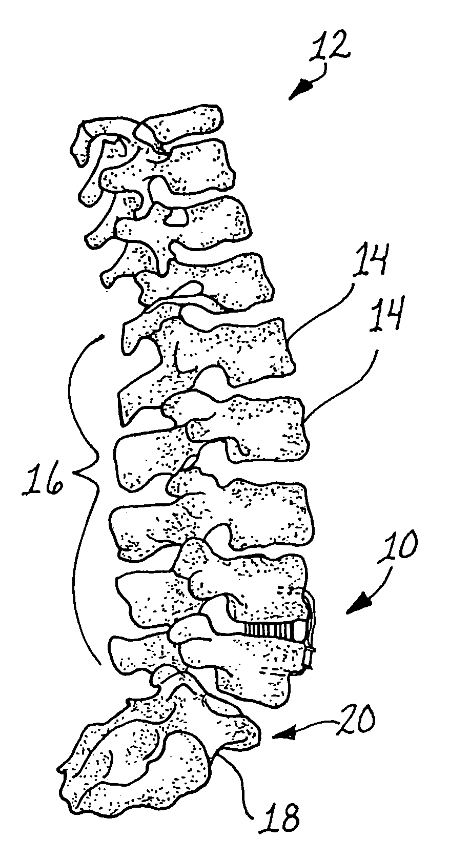
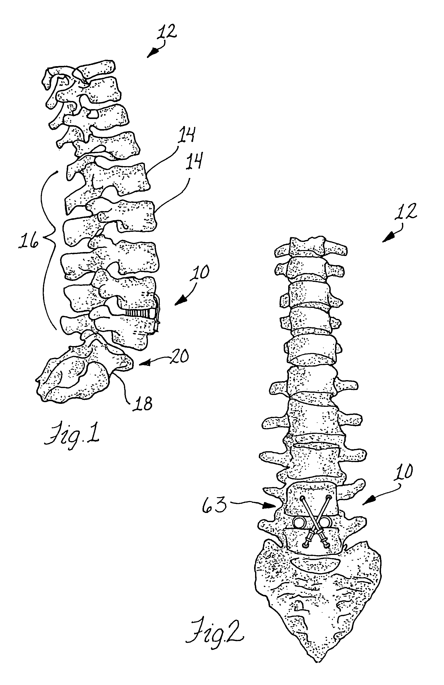
[0023]In FIGS. 1 and 2, a bone fixation system 10 is shown used on the spinal column 12, and more particularly on vertebrae bones 14 in the lower lumbar region 16 of the spine 12. The system 10 in typical usage is applied to the vertebrae bones 14 of the lower lumbar region 16, such as between the L4 and L5 vertebrae 14 as illustrated, as well as between the composite vertebrae bones 18 in the sacrum region 20 of the spinal column 12, i.e. the L5 and S1 vertebrae bones.

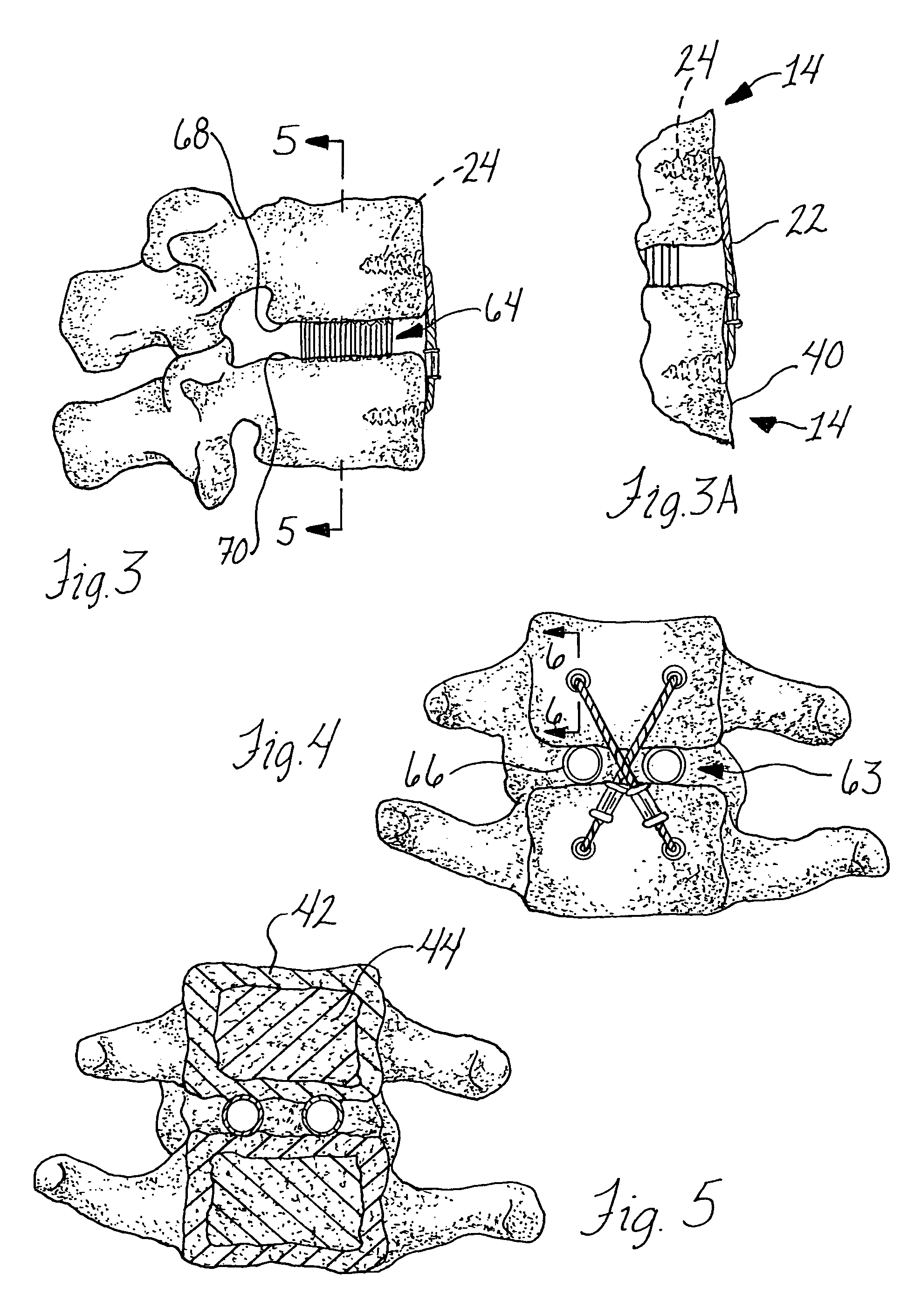
[0024]The bone fixation system 10 herein utilizes flexible cables 22 that are secured to the bones 14 by anchor members 24 (FIG. 3), preferably in the form of screw anchors 26, as shown in FIGS. 7A and 7B. The screw anchors 26 include a shank 28 preferably of a cancellous material and that is threaded with external threads 30 for substantially its entire length from the proximate end 32 to the distal end 34 thereof, as can be seen in FIGS. 8 and 10. In this regard, the screw anchors 26 are preferably headless and can ...


PUM


Abstract

A system and method for maintaining positions of bones fixed or approximated relative to each other is provided that is ideal for minimizing interference with surrounding viscera in spinal column procedures, although other good application therefor are also disclosed. In the preferred form, a cable anchoring apparatus in the form of a screw member having an elongate shank that is threaded for substantially the full length thereof is employed. An internal driver surface is provided so that the size of the proximate end of the shank can be minimized or maintained consistently sized with respect to the reminder of the shank with no enlarged driver head formed thereat. This allows the amount of bone material that is removed from full insertion of the screw anchor to be minimized, i.e. no countersinking for an enlarged driver head is necessary, thus improving holding power of the cable anchor herein. Further, the full threading of the shank for substantially its entire length enables the screw member to be fully sunk into the bone so that no portions thereof, such as an enlarged screw head, project into the surrounding body cavity in which the bone is located. In the spinal column application, a criss-cross cable pattern is disclosed to better resist torsional forces and keep any decompression devices in place in the gap between adjacent vertebrae.

Description

CROSS REFERENCE TO RELATED APPLICATION[0001]This is a division of prior application Ser. No. 10 / 007,146, filed Dec. 3, 2001 now U.S. Pat. No. 6,730,092, which is hereby incorporated herein by reference in its entirety.FIELD OF THE INVENTION[0002]The invention relates to a bone fixation system and method and, more particularly, to a cable anchoring apparatus for using cables to stabilize bones relative to each other.BACKGROUND OF THE INVENTION[0003]It is known to use cables anchored to bones for various medical procedures. For example, with respect to the spinal column, several applications are apparent. However, one significant limitation with these applications is the need for posterior procedures, particularly where anterior procedures would be preferable, but whose performance is limited by the space required of current cable anchors in the body cavity. Anterior along the spinal column are significant impediments to having cable anchor members projecting from the vertebrae in whi...

Claims


Application Information

Patent Timeline
Patent Type & Authority Patents(United States)
IPC IPC(8): A61B17/58A61BA61B17/04A61B17/70A61B17/86A61F2/30
CPCA61B17/0401A61B17/7022Y10S606/90A61B17/0487A61B17/864A61B2017/0409A61B2017/0414A61B2017/044A61B2017/0445A61B2017/0454A61B2017/0488A61B2017/0496A61B2017/7073Y10S606/907A61B17/0469
Inventor SONGER, MATTHEW N.
Owner PIONEER SURGICAL TECH INC
Learn More