Connected screens for vibratory separators

a vibratory separator and screen technology, applied in the direction of filtration separation, separation process, moving filter element filter, etc., can solve the problem of difficult removal of screen assemblies, and achieve the effect of improving the sealing

Inactive Publication Date: 2006-10-05
VARCO I P INC
View PDF44 Cites 46 Cited by
  • Summary
  • Abstract
  • Description
  • Claims
  • Application Information

AI Technical Summary

Benefits of technology

[0023] Such systems and methods that provide an enhance

Problems solved by technology

Often removal of these screen assemblies can be difficult, particularly the removal of those fa

Method used


Image

  • Connected screens for vibratory separators
  • Connected screens for vibratory separators
  • Connected screens for vibratory separators

Examples


Embodiment Construction

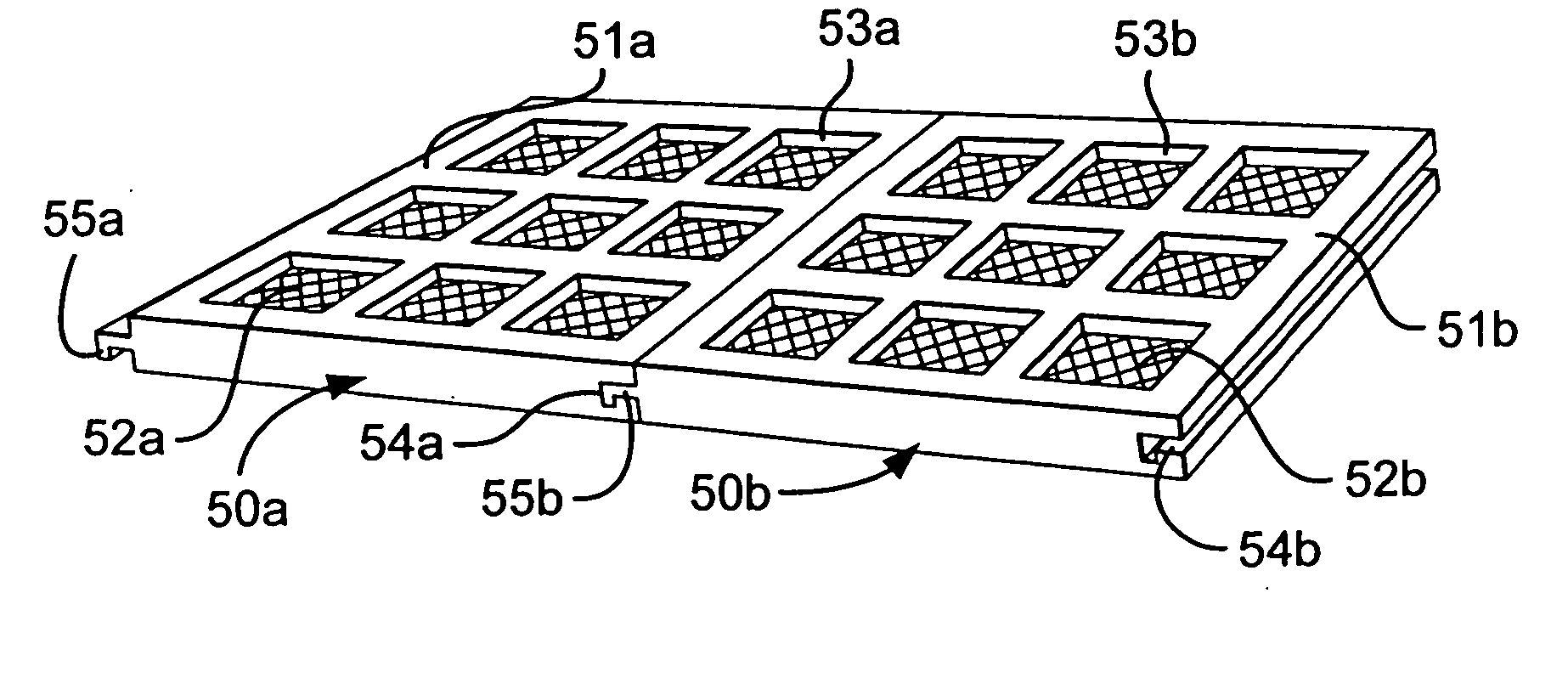
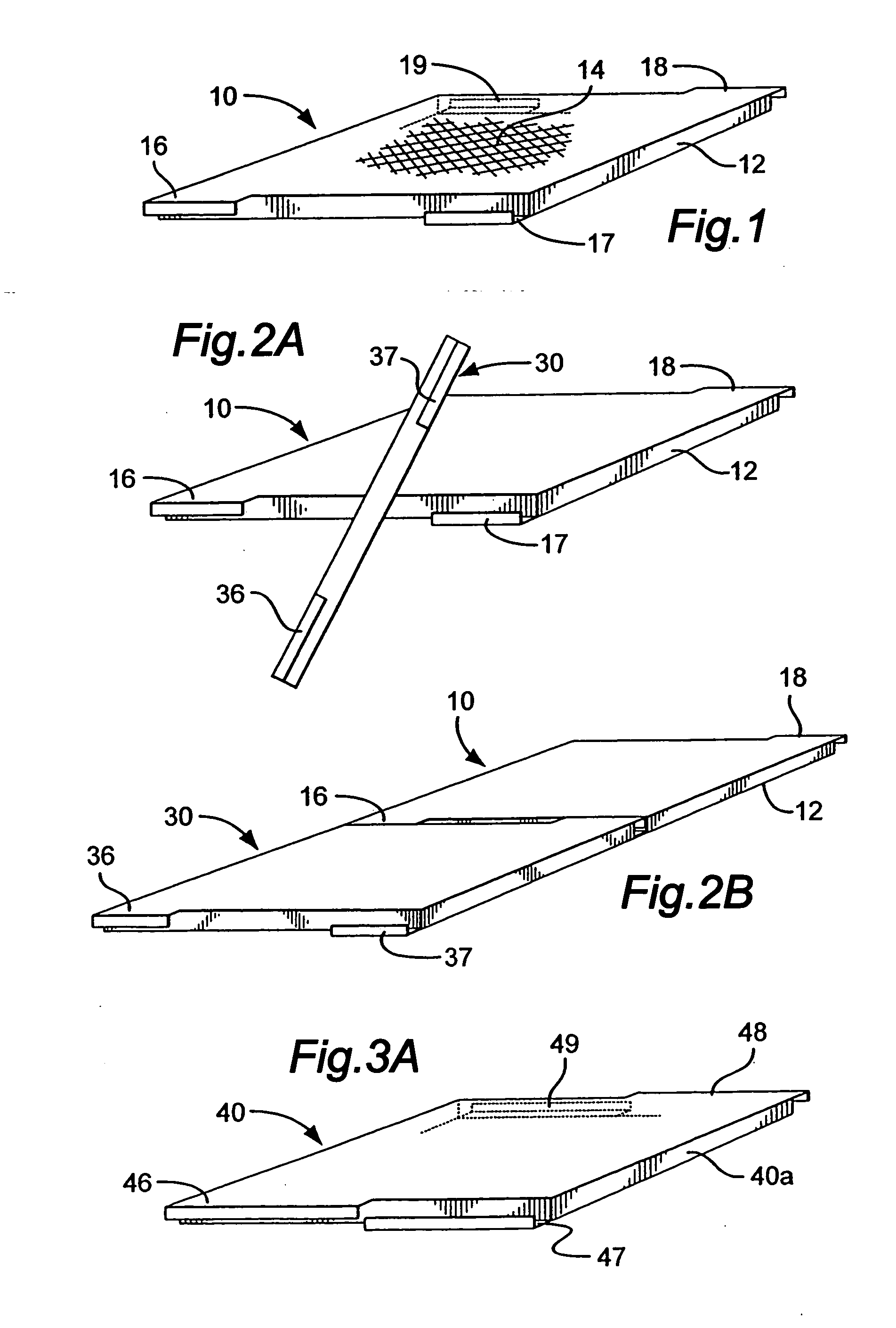
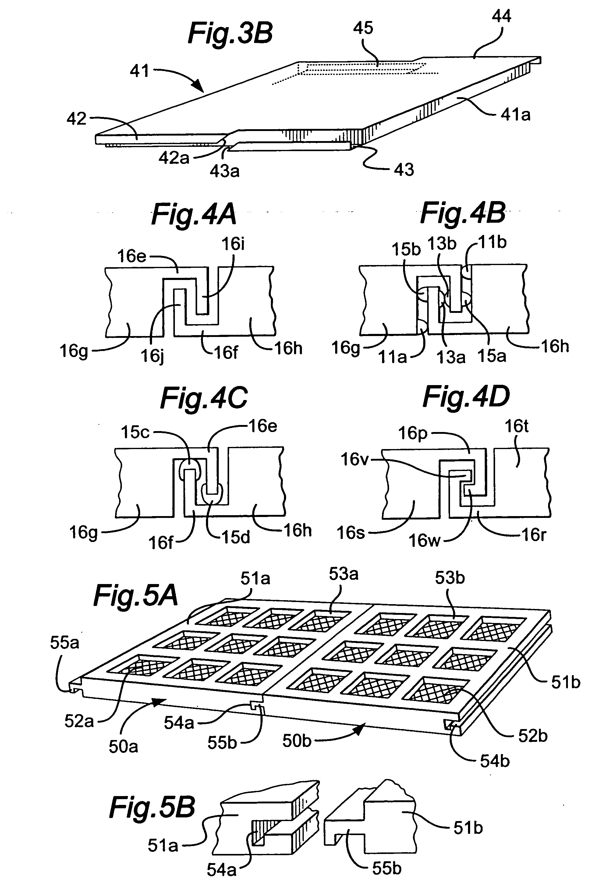
[0125]FIG. 1 shows schematically a screen assembly 10 according to the present invention for a vibratory separator or shale shaker which has a support or frame 12 with screening material 14. It is to be understood that it is within the scope of the present invention for side and / or cross members of the support or frame 12 to be like any such known support or frame members, including but not limited to, those of supports and frames in U.S. Pat. Nos. 5,417,793; 5,417,859; 5,417,858; 6,443,310; 6,439,392 and in the prior art cited therein. According to the present invention end members 16, 17, 18 and 19 of the frame 12 have lips and projecting therefrom. Each lip has a vertical portion connected to a horizontal portion . Such portions can be added to, secured to or formed integrally of any suitable known support or frame member to effect a frame or support according to the present invention. Alternatively, the lips may be generally curved with no portion at an abrupt angle to the other...


PUM

PropertyMeasurementUnit
Lengthaaaaaaaaaa

Abstract

Interconnectible screen assemblies for vibratory separators or shale shakers and methods for manipulating such screen assemblies which, in certain aspects, include a first screen assembly and a second screen assembly positioning at least a portion of the first screen assembly with respect to the second screen assembly, releasably connecting the second screen assembly to the first screen assembly, and moving the first screen assembly and the second screen assembly together.

Description

CROSS-REFERENCE TO RELATED APPLICATIONS [0001] This is a continuation-in-part of U.S. patent application Ser. No. 11 / 301,349 filed Dec. 12, 2005; Ser. No. 10 / 359,733 filed Feb. 4, 2003; and Ser. No. 10 / 429,290 filed May 1, 2003—from all of which the present invention claims priority under the Patent Laws and all of which are incorporated fully herein for all purposes.BACKGROUND OF THE INVENTION [0002] 1. Field Of The Invention [0003] The present invention is directed to screens and screen assemblies for vibratory separators and shale shakers, to screen assembly seals and holders and mounts for them, to releasably connectible screens and screen assemblies, and to methods of mounting them within and removing them from such separators and shakers. [0004] 2. Description of Related Art [0005] The prior art discloses a variety of screen assembly mounting structures for holding screen assemblies in position. In many instances screen assemblies are positioned sequentially on or within mount...

Claims


Application Information

Patent Timeline
IPC IPC(8): B07B1/49
CPCB01D33/0376B01D2201/40B07B1/46B07B1/4609B07B1/4663B07B1/4645B01D33/37
Inventor SCOTT, ERICSCHULTE, DAVID L. JR.MCCLUNG, GUY L. III
Owner VARCO I P INC
Why Eureka
Try Eureka