Magnet retention on rotors

a magnet and rotor technology, applied in the direction of magnetic circuit rotating parts, dynamo-electric machines, magnetic circuit shape/form/construction, etc., can solve the problems of high centrifugal force, difficult magnet retention, brittle ceramics of magnets,

Active Publication Date: 2006-10-05
MOOG INC
View PDF18 Cites 56 Cited by
  • Summary
  • Abstract
  • Description
  • Claims
  • Application Information

AI Technical Summary

Problems solved by technology

Magnet retention is difficult, involving several factors.
First, the magnets are brittle ceramics and structurally weak.
Second, the centrifugal forces are high, especially with very high-speed rotors.
Third, radial space (i.e., the space between the rotor and the stator) is at a premium because the magnetic field weakens as the radial separation between the rotor and stator increases.
Fourth, permanent magnet motors frequently are required to operate in environments spanning a wide range of temperatures and the rates of thermal expansion of the components of the rotor may differ substantially over the temperature range.
These methods have a drawback in that the thickness of the wrap reduces the mechanical clearance (i.e., the radial space) between the stator and rotor.
Also, the expansion rate of the wrap under tension and temperature makes it difficult to keep the adhesive bond in compression at high rotational speed.
Finally, since these approaches depend on the integrity of the outer wrap, it is not feasible to repair or replace a magnet after the rotor has been built.
This is an expensive approach, and the thickness of the box subtracts from the radial clearance between the rotor and stator.
Interior magnet constructions require compromises in the magnetic circuit that reduce performance in some applications.

Method used


Image

  • Magnet retention on rotors
  • Magnet retention on rotors
  • Magnet retention on rotors

Examples


Embodiment Construction

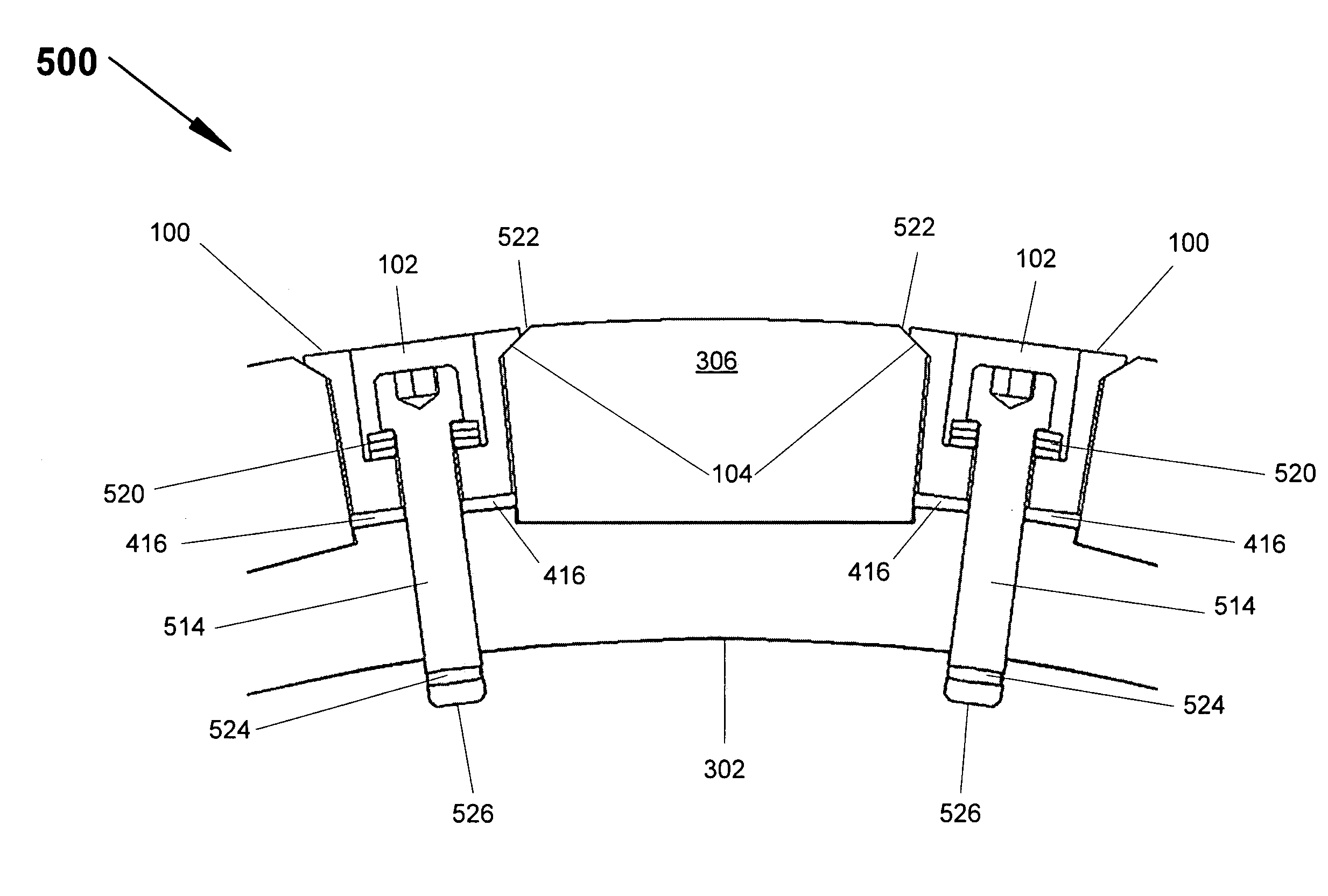
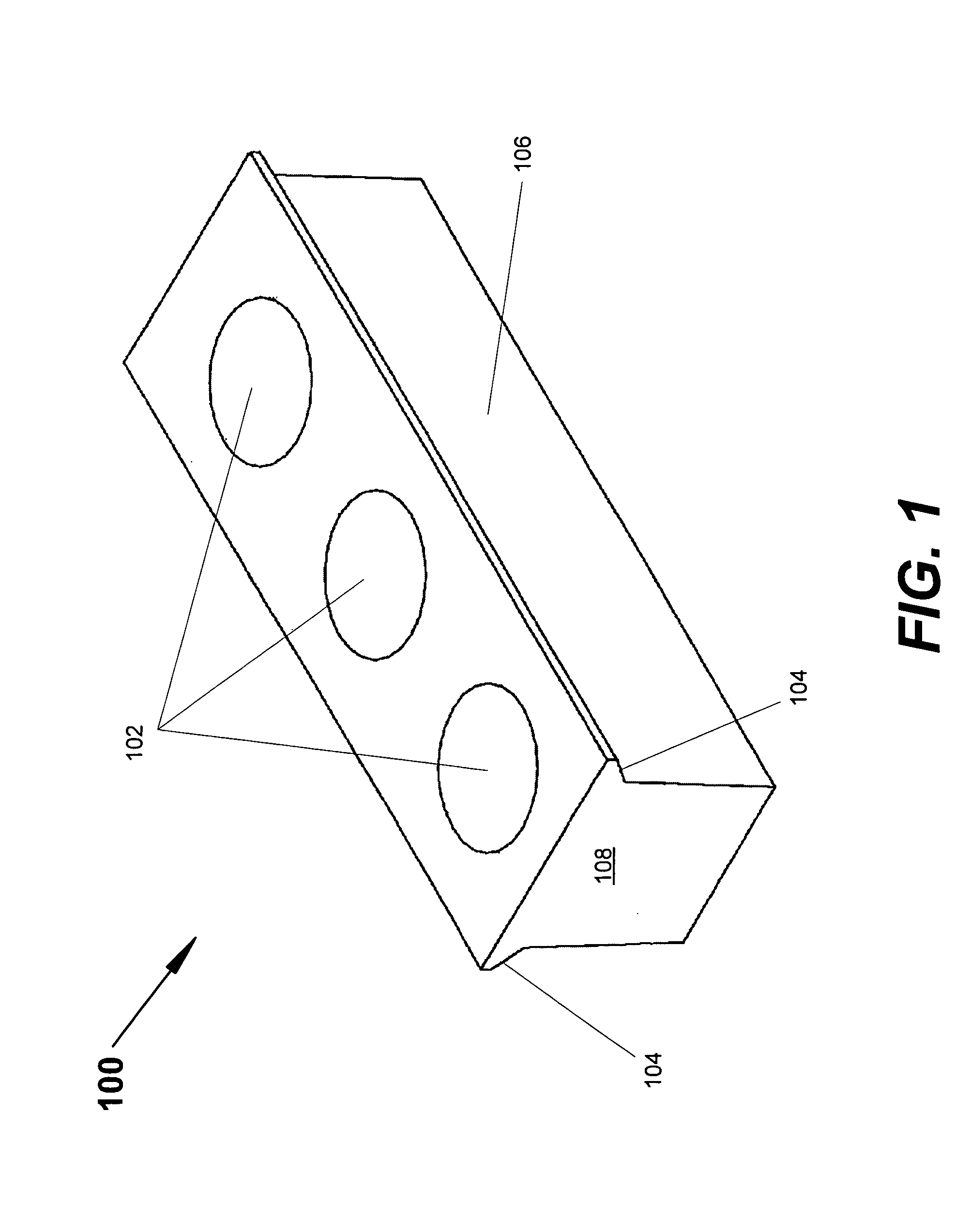
[0020] The present invention provides for improved retention of magnets on rotors useful in permanent magnet motors. In accordance with the present invention, magnet retainers are advantageously utilized to aid in retaining magnets onto a rotor body that has a cylindrical surface. The magnets are disposed on the cylindrical surface at equal intervals around the circumference of the cylindrical surface. An adhesive layer is disposed between the magnet and the cylindrical surface. Magnet retainers are disposed between each pair of magnets and secured to the rotor body. The magnet retainers are secured to the rotor body in a manner that applies a centripetal force on the magnets, pulling the magnets down onto the cylindrical surface of the rotor body in a manner that exerts a compressive force on the adhesive layer even at the highest rotational speeds at which the rotor is used. Spring mechanisms are used to counter centrifugal force on the magnets during use (i.e., rotation of the ro...


PUM


Abstract

Permanent magnets are mounted on a rotor of an electrical motor by an apparatus that keeps an adhesive bonding layer between the magnet and rotor in compression over wide variations in temperature and speed of rotation. The mechanical stresses on the magnets are controlled using compliant layers and spacers. The apparatus allows the removal and replacement of individual magnets.

Description

[0001] This application claims the benefit of the filing date of U.S. Provisional Application; Ser. No. 60 / 666,539; filed Mar. 30, 2005; entitled “Method and Apparatus for Retention of Magnets on a Permanent Magnet Motor Rotor,” the entirety of which provisional application is incorporated herein by reference.FIELD OF THE INVENTION [0002] The present invention relates generally to permanent magnet motors. More particularly, the present invention relates to retaining magnets on rotors useful in permanent magnet motors. BACKGROUND OF THE INVENTION [0003] A permanent magnet motor consists of a wound stator within which a rotor rotates. Permanent magnets are attached to the rotor to produce alternating north and south magnetic fields that interact with electrical current through the stator to produce torque. The permanent magnets are attracted to the steel core of the rotor, but the centrifugal force created by the rotation of the rotor tends to pull the magnets off of the rotor. [0004]...

Claims


Application Information

Patent Timeline
Patent Type & Authority Applications(United States)
IPC IPC(8): H02K21/12H02K1/27
CPCH02K1/278
Inventor JONES, STUART A.JONES, FRANKLIN B.
Owner MOOG INC
Why Eureka
Try Eureka