

Digital camera capable of continuous shooting and control method for the digital camera
a digital camera and continuous shooting technology, applied in the field of digital cameras, can solve problems such as becoming very burdensom
- Summary
- Abstract
- Description
- Claims
- Application Information
AI Technical Summary
Benefits of technology
Problems solved by technology
Method used
Image

Examples
first embodiment
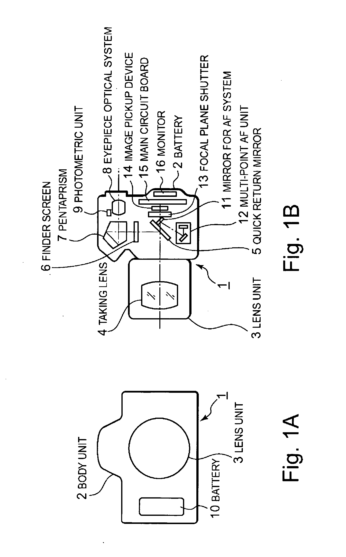
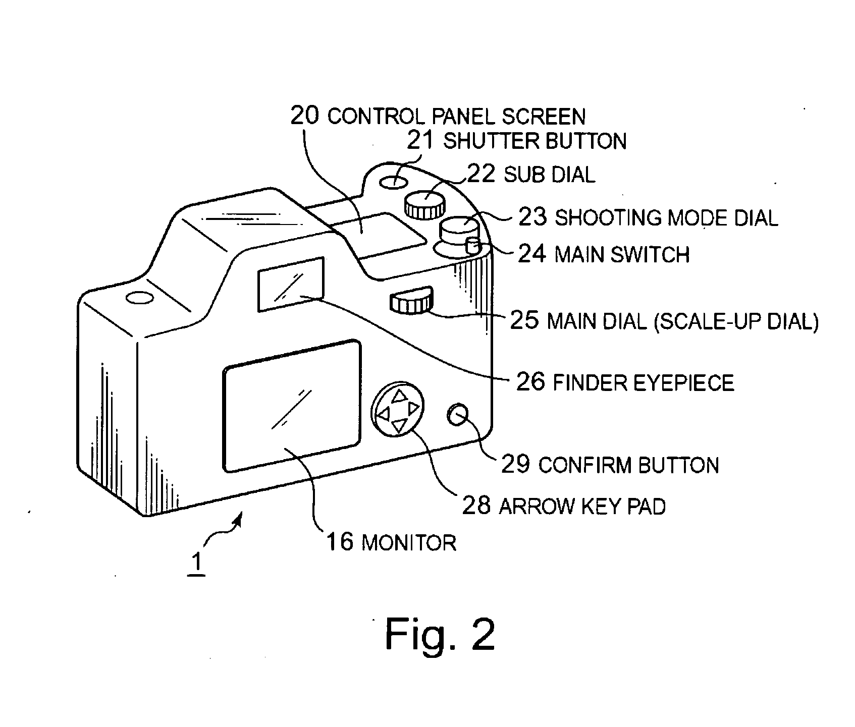
[0045]FIG. 1 shows the schematic structure of a digital camera according to a first embodiment of the present invention. Specifically, FIG. 1A is a front view of the digital camera and FIG. 1B is a side view of the digital camera. FIG. 2 is a perspective view of the appearance of the digital camera of FIG. 1 as viewed from its backside.
[0046] As shown in FIGS. 1A and 1B, this digital camera 1 has a body unit 2 and a lens unit 3 mountable on the body unit 2.
[0047] The lens unit 3 consists of a plurality of lenses, including a taking lens 4 for guiding a flux of light to an image pickup device 14 in the body unit 2 as described later.
[0048] On the other hand, a battery 10 is provided in the body unit 2 to supply power to each component in the body unit 2. A quick return mirror (reflecting mirror) 5 is provided on the optical path of the flux of light passing through the taking lens 4 to reflect the light flux. On the optical path of the reflected light from the quick return mirror ...
second embodiment
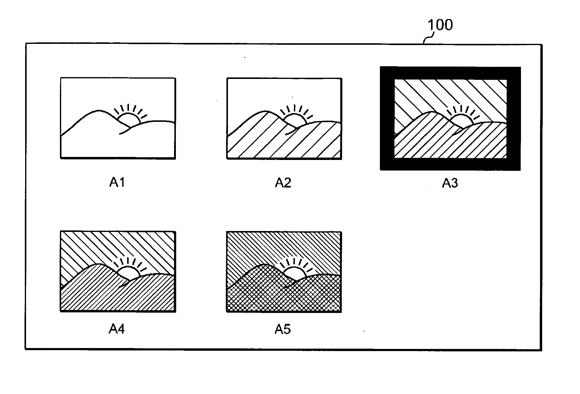
[0088] A second embodiment features that a plurality of continuous shots on a multi-index display, that is, all continuous shots captured in the continuous shooting mode and displayed on one screen, are scaled up based on each focusing point, which varies from shot to shot according to the movement of a subject. Since the basic structure of the second embodiment is the same as that of the first embodiment (FIGS. 1 to 3), the following describes only a sequence of operations specific to the digital camera according to the second embodiment.
[0089] The imaging operation of the digital camera according to the second embodiment of the present invention is described in detail below with reference to the flowchart of FIG. 14. The following description may refer to the structural elements of FIGS. 1 to 3.
[0090] When the imaging operation is started in an imaging mode, the control circuit 40 first controls the photometric circuit 46 to perform exposure metering and calculation (step S101)....
third embodiment
[0096] The imaging operation of a digital camera according to a third embodiment of the present invention is described in detail below with reference to a flowchart of FIG. 15. The following description may refer to the structural elements of FIGS. 1 to 3. The digital camera of the third embodiment has a bracketing mode.
[0097] First, the control circuit 40 determines whether the operator presses the shutter button 21 halfway to turn on 1R (step S201). If 1R is on, the multi-point AF unit 12 performs multi-point AF to measure distances to subjects at a plurality of points on the finder screen so that the nearest subject will be focused (step S202). Further, the photometric unit 9 performs light metering to calculate exposure conditions based on the metering results (step S203).
[0098] The control circuit 40 then determines whether the brightness of the subject is appropriate (e.g., whether it is equal to or less than a predetermined threshold value) (step S204). If it is not appropr...
PUM
 Abstract
Description
Claims
Application Information