Patient immobilization device with diagnostic capabilities

a technology of immobilization device and diagnostic capability, applied in the field of patient immobilization device, can solve the problems of difficult storage, lost or misplaced items, premature deterioration of blocks and their covering or outer skin, etc., and achieve the effect of improving diagnostic evaluation

Inactive Publication Date: 2006-10-12
TOMCANY BRIAN
View PDF73 Cites 24 Cited by
  • Summary
  • Abstract
  • Description
  • Claims
  • Application Information

AI Technical Summary

Benefits of technology

The present invention allows medical professionals to quickly and accurately evaluate different situations that patients are facing after an accident. This is done while keeping the patient stable and without having to leave them behind or look away from their face. Overall, this improves the process of diagnosis for traumatized individuals.

Problems solved by technology

The technical problem addressed by this patent is the need for a more efficient and effective patient immobilization device that minimizes interruptions for medical professionals while still providing adequate protection for patients. Current methods involve multiple components and require frequent maintenance, leading to increased costs and potential safety issues. Additionally, current devices make it challenging for medical professionals to access necessary reference materials without having to leave the patient unattended.

Method used


Image

  • Patient immobilization device with diagnostic capabilities
  • Patient immobilization device with diagnostic capabilities
  • Patient immobilization device with diagnostic capabilities

Examples


Embodiment Construction

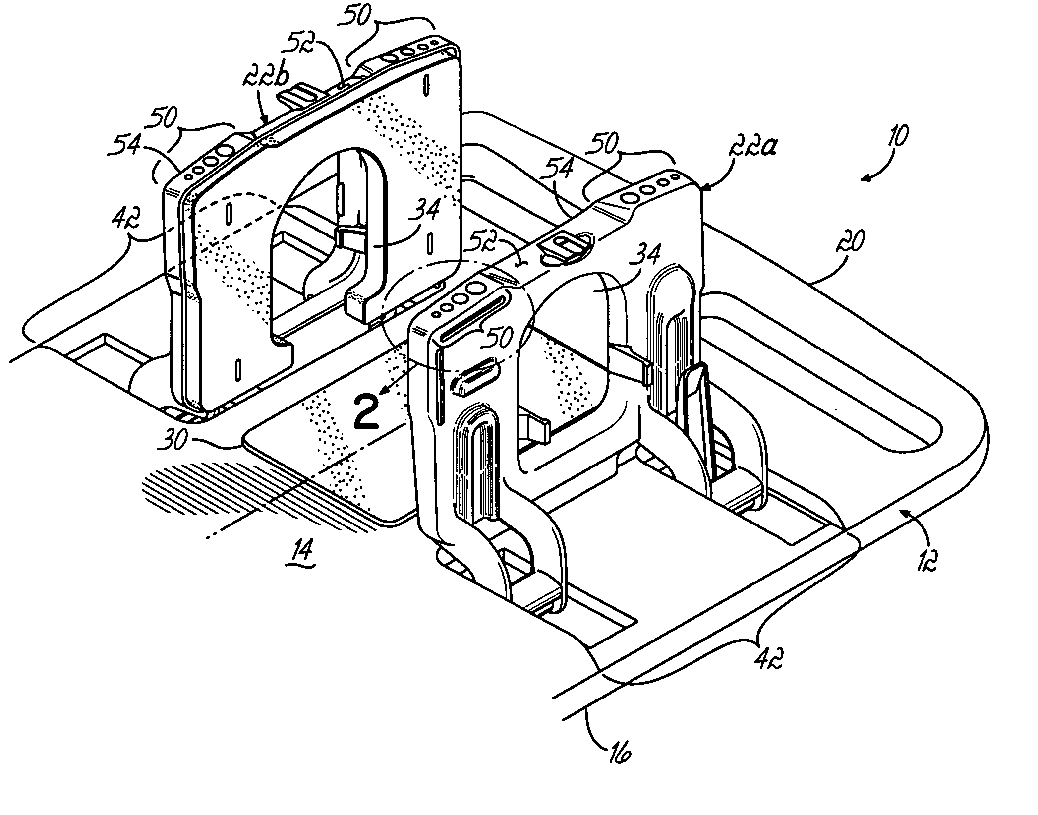
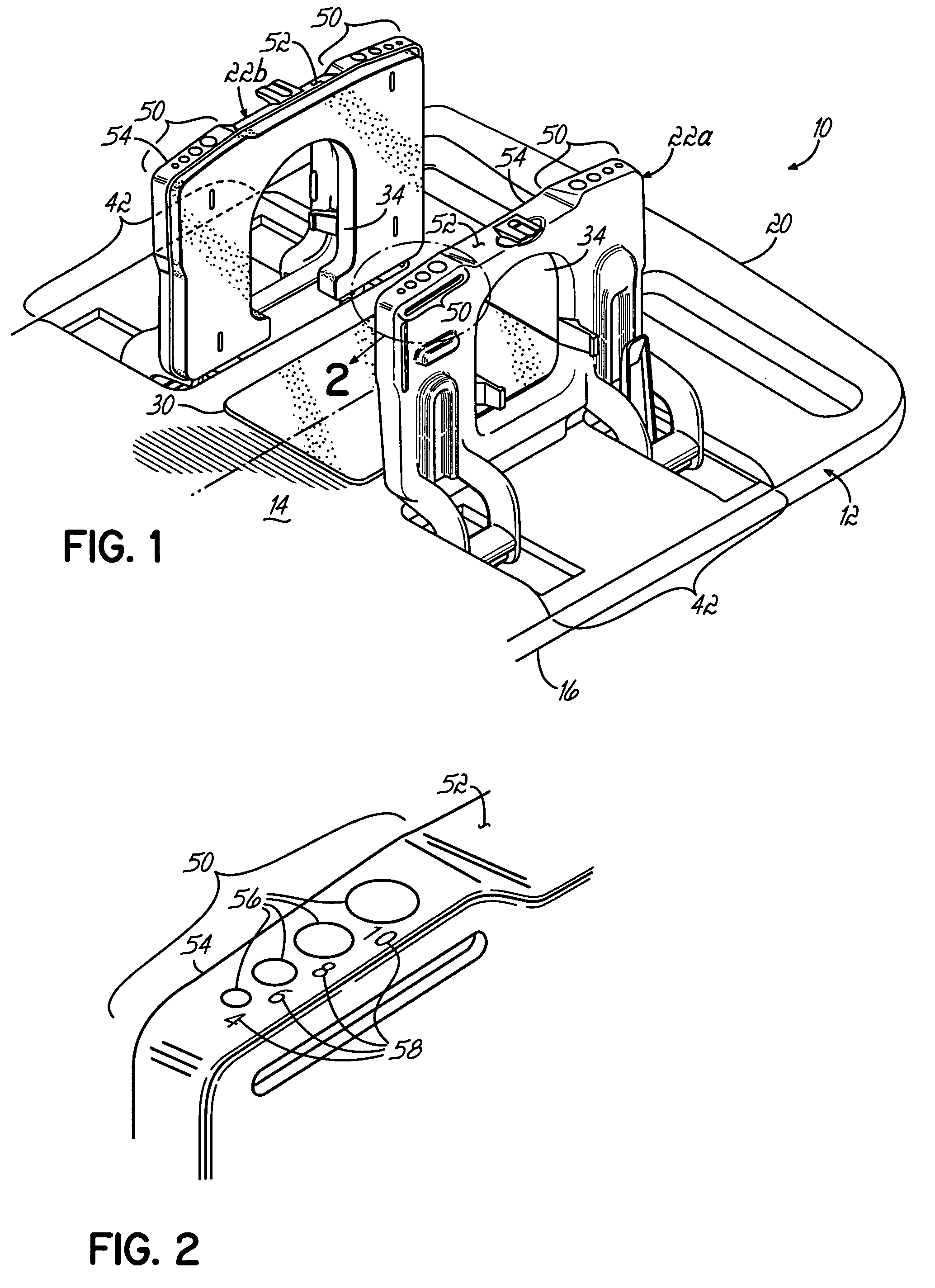
[0022] Referring to FIG. 1, a perspective view of an embodiment of a patient immobilization device 10 of the invention is illustrated. Generally, such a device comprises a backboard or backboard portion 12, having a top side or front side 14, and a bottom side or back side 16. The view of FIG. 1 shows a broken away section (namely the head section) of a backboard 12. It will be understood by a person of ordinary skill in the art that the backboard 12 is generally elongated to hold a patient's body, although the entire length is not shown in the Figures. In use, a patient would generally be placed on the front side 14, with their feet at a foot end (not shown) of the backboard and their head at the head end 20 of the backboard. For securing the head and neck of a patient, the invention utilizes a structure configured to support the head and neck. In one aspect, the structure may be manipulated from a storage position to a support position for use. In one embodiment, the support struc...


PUM


Abstract

A patient immobilization device for immobilizing a patient and performing a diagnostic evaluation of such patient is comprised of a backboard, a structure configured to support the head of a patient on the backboard, and a pupil-sizing indicator positioned on a surface of the support structure to be visually accessible to a person that is visually evaluating the head and face of an immobilized patient on the backboard.

Description


Claims


Application Information

Patent Timeline
Owner TOMCANY BRIAN
Why Eureka
Try Eureka