Thermoelectric-based heating and cooling system

a technology of heating and cooling system and thermoelectric module, which is applied in the direction of domestic cooling apparatus, lighting and heating apparatus, and machine operation mode, etc., can solve the problems of reducing the service life of the heat exchanger

Active Publication Date: 2006-10-12
GENTHERM INC
View PDF19 Cites 111 Cited by
  • Summary
  • Abstract
  • Description
  • Claims
  • Application Information

AI Technical Summary

Benefits of technology

[0007] In overcoming the drawbacks and limitations of the known technologies, a system of heating and cooling the passenger compartment of an automobile is disclosed. The heating and cooling system includes a first circuit and a second circuit. The first circuit includes a first pump for circulating a first medium therethrough, a first heat exchanger and a th

Problems solved by technology

The drawback with this is that the heat exchanger will not provide heat until the engine has caused the coolant to warm up.
I

Method used


Image

  • Thermoelectric-based heating and cooling system
  • Thermoelectric-based heating and cooling system
  • Thermoelectric-based heating and cooling system

Examples


Embodiment Construction

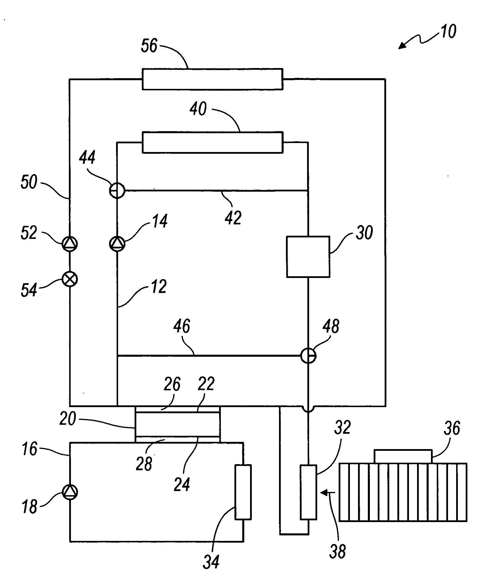
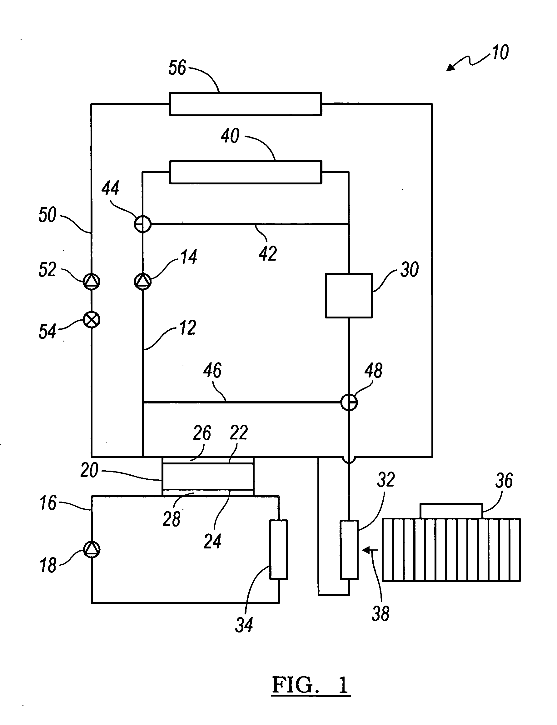
[0018] Referring to FIG. 1, the various components of a HVAC unit 10 are shown. The HVAC unit 10 includes a first circuit 12 having a first pump 14, a second circuit 16 having a second pump 18, and a thermoelectric module 20 having a first surface 22 and a second surface 24 in thermal communication with the first and second circuits 12, 16, respectively. The first pump 14 circulates a first medium through the first circuit, and the second pump 18 circulates a second medium through the second circuit 16.

[0019] In the context of this description, the term “pump” is used in its broad sense of its ordinary and customary meaning and further includes any conventional pump, J×B (J Cross B) pump, electrostatic pump, centrifugal pump, positive displacement pump, gear pump, peristaltic pump or any other medium moving device or combination thereof that is known or later developed.

[0020] Generally, the first and second mediums are a liquid having a mix of water and glycol. Alternatively, the ...


PUM

PropertyMeasurementUnit
Phaseaaaaaaaaaa
Temperature coefficient of refractive indexaaaaaaaaaa
Heataaaaaaaaaa

Abstract

Disclosed is a heating, ventilation and air conditioning system for a vehicle that operates in a heating mode, a cooling mode or a demisting mode. The system includes a first circuit having first pump for circulating a first medium therein, a second circuit having a second pump for circulating a second medium therein and a thermoelectric module having a first surface in thermal contact with the first medium and a second surface in thermal contact with the second medium.

Description

BACKGROUND [0001] 1. Field of the Invention [0002] The present invention generally relates to heating, ventilation and air conditioning (“HVAC”) systems for a vehicle, and more particularly to HVAC systems having thermoelectric modules for providing heating and cooling to a passenger compartment of the vehicle. [0003] 2. Description of the Known Technology [0004] In a conventional vehicle, such as an automobile, the heating of the passenger compartment is accomplished by running engine coolant, typically a mix of water and glycol, through a heat exchanger and then blowing air through the heat exchanger and into the passenger compartment. The drawback with this is that the heat exchanger will not provide heat until the engine has caused the coolant to warm up. In colder climates, the time to warm up the coolant can be lengthy, thereby delaying warming of passengers of the automobile. [0005] Furthermore, newer engines and powertrain arrangements are being developed where the engine do...

Claims


Application Information

Patent Timeline
IPC IPC(8): B60H3/00F25B1/00
CPCB60H1/00478B60H1/2221B60H2001/2275Y10T29/49002F25B27/02F25B2321/0252B23P15/26F25B21/04Y02A30/274
Inventor GOENKA, LAKHI N.CRANE, DOUGLAS T.BELL, LON E.
Owner GENTHERM INC
Why Eureka
Try Eureka