Foldably constructed force-resisting structures

a technology of force-resisting structure and folding support, which is applied in the field of folding support, can solve the problems of reducing the overall cost effectiveness of palletized shipments, and increasing the cost of making and repairing wooden pallets,

Active Publication Date: 2006-10-12
DESIGN PALLETS
View PDF9 Cites 24 Cited by
  • Summary
  • Abstract
  • Description
  • Claims
  • Application Information

AI Technical Summary

Benefits of technology

[0014] The bottom member can have a plurality of interior support flaps foldably connected to the bottom member base panel. The plurality of interior support flaps may include one or more central interior support flaps located toward the center or middle of the bottom member base panel and one or more outer interior support flaps located toward the sides of the bottom member base panel. The separable flap segments of different interior support flaps may be interlocking secured to one another. The separable flap segments may be interlockingly secured to other portions of the top member and/or the bottom member. The plurality of interior support flaps may be arranged to form an interior vertical support structure or assembly of various configurations when the support flaps are folded to the angled position.
[0015] In one embodiment of the force-resisting structure in which the top and bottom members are each formed as a separate blank, the top member includes at least one side portion foldably connected to a side edge of the top member base panel and having an access opening therein and/or the top member includes at least one retention element foldably connected to a side edge of the top member base panel. Where the top member includes a side portion with an access opening, the bottom member includes a retention element foldably connected to a side edge of the bottom member base panel in correspondence with the access opening of the top member. Where the top member includes a retention element, the bottom member includes a side portion foldably connected to a side edge of the bottom member base panel and having an

Problems solved by technology

However, a number of problems face present day users of conventional wooden pallets.
The rising cost of making and repairing wooden pallets has detracted from the overall cost effectiveness of palletized shipments.
Wooden pallets are heavy, bulky and cumbersome, and empty wooden pallets require substantial storage space.
It is especially costly to transport empty wooden pallets by rail or truck for reuse.
To save costs, conventional wooden pallets purchased and used by shippers are ordinarily returned to the shipper for reuse, but since wooden pallets are heavy, bulky and cumbersome, they are inconvenient to store and relatively expensive to return to the shipper.
Generally speaking, landfill or other waste disposal sites will not accept wooden pallets as is; rather, the pallets must first be reduced either by chipping or burning prior to disposal.
Chipping adds significant cost to wooden pallet disposal, and burning wooden pallets is often precluded by environmental regulations.
The market for recycled wooden pallets is limited, however, because many retailers refuse to receive goods transported on recycled wooden pallets due to the lack of any standards regulating the quality of the repair or refurbishment of used wooden pallets.
Pallets constructed of plastic or metal have been proposed, but plastic and metal pallets have many of the same disadvantages as wooden pallets including being heavy, bulky and cumbersome, being costly and inconvenient to transport, store and dispose of, and being incompatible with environmental preservation.
Since an individual pallet ordinarily includes a plurality of vertical supports, the need to apply an extraneous fastener to each vertical support adds to the cost, time, labor and complexity involved in constructing or assembling the pallet.
Furthermore, paperboard

Method used


Image

  • Foldably constructed force-resisting structures
  • Foldably constructed force-resisting structures
  • Foldably constructed force-resisting structures

Examples


Embodiment Construction

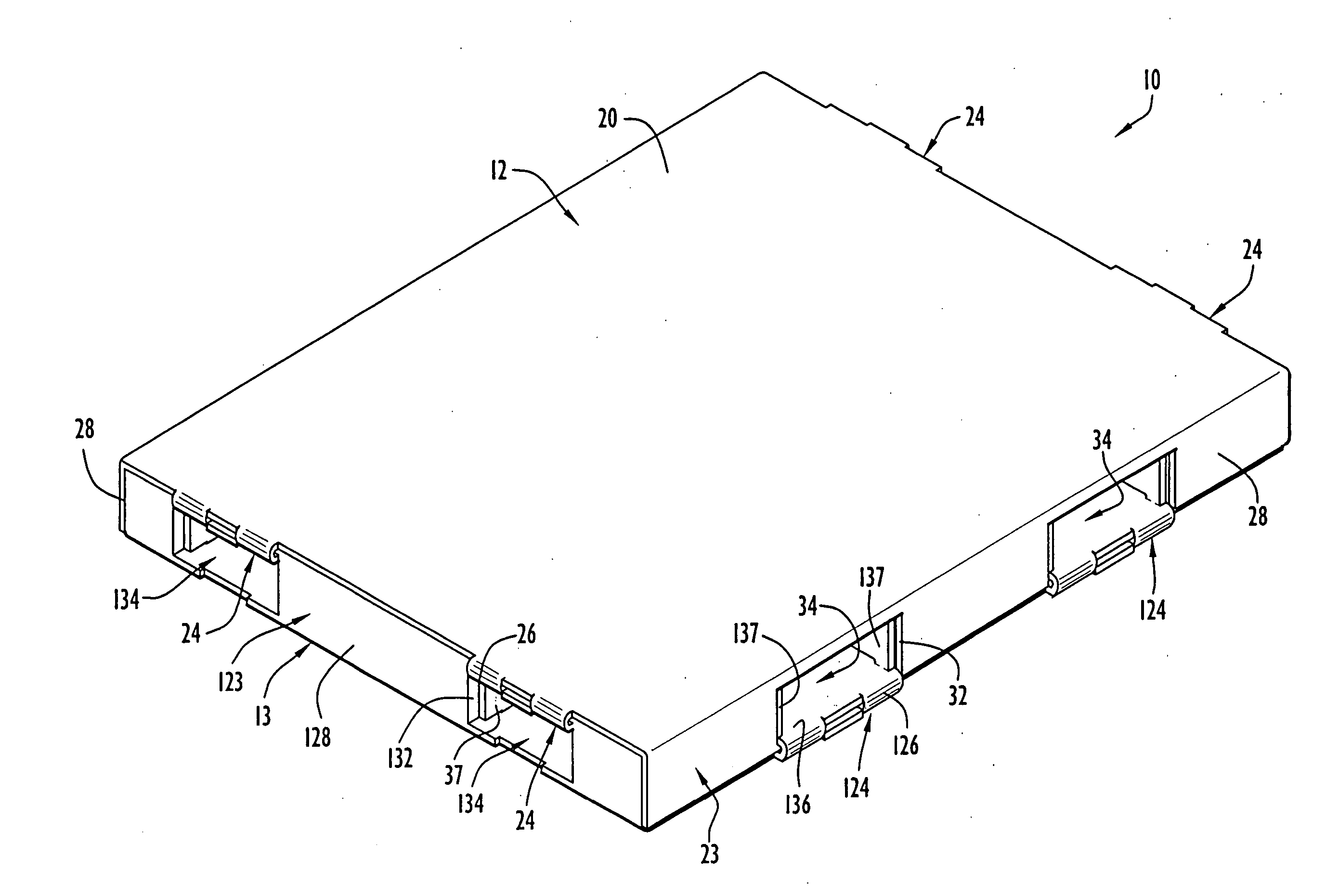
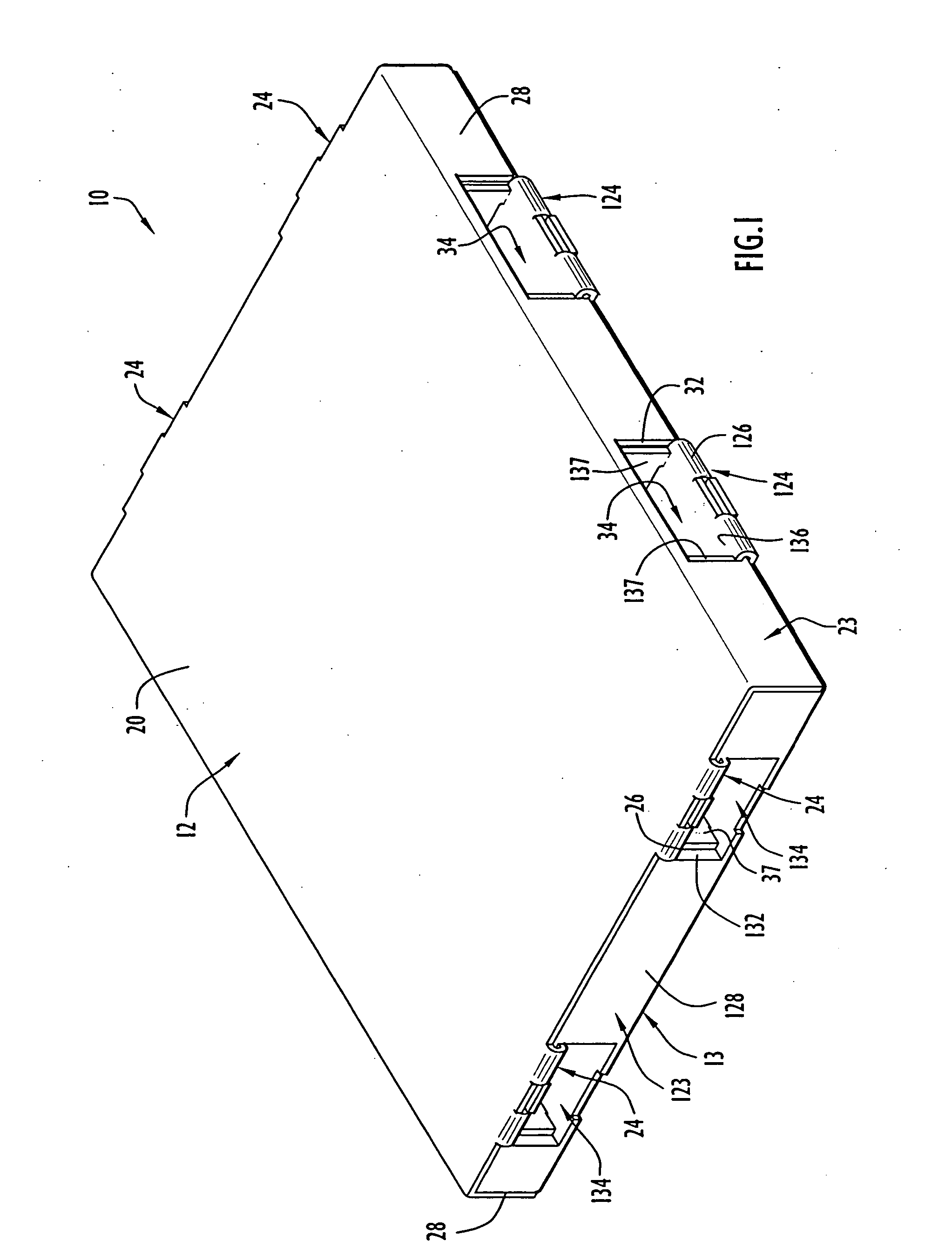
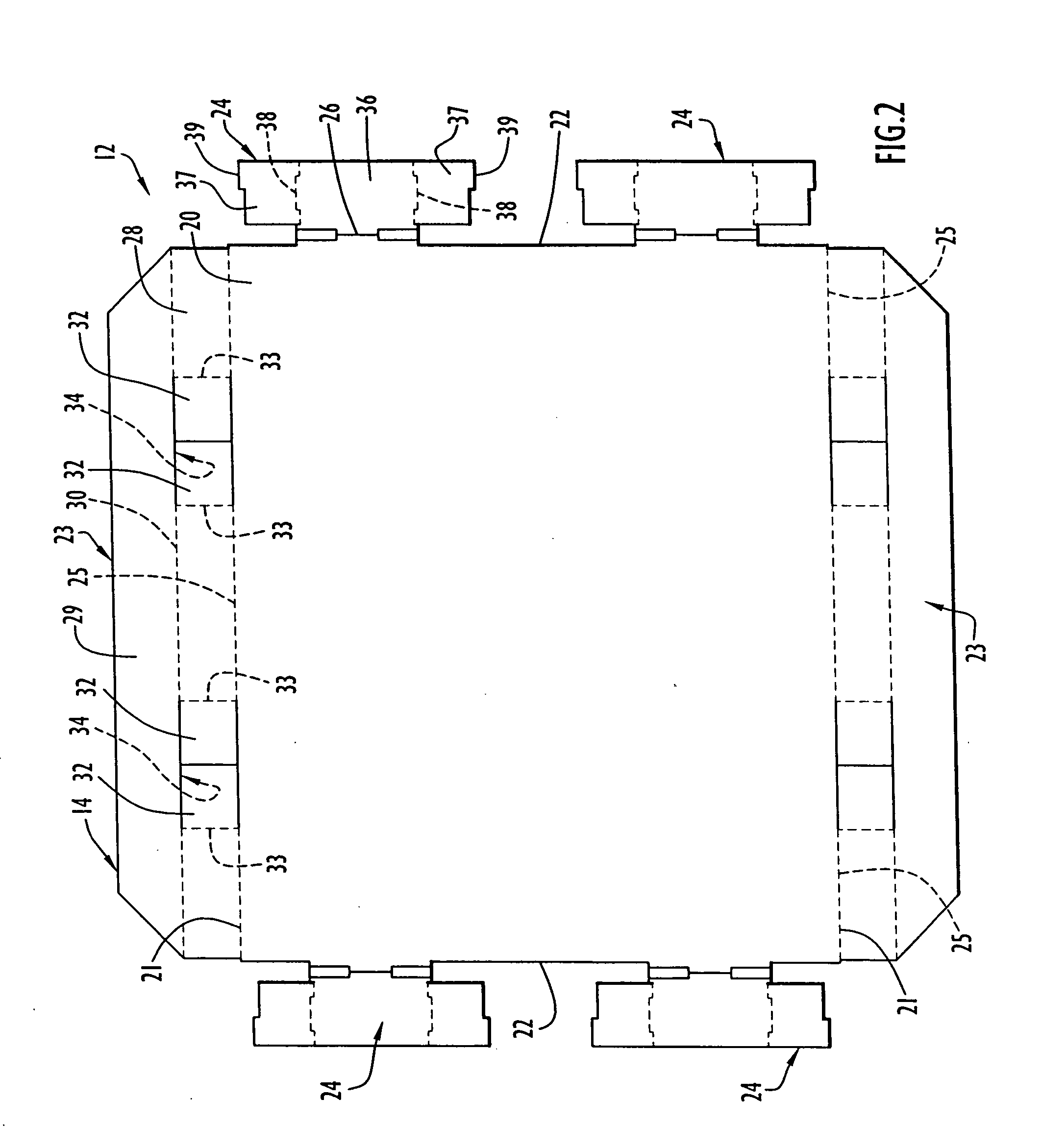
[0040] A foldably constructed or assembled force-resisting structure or support 10 according to the present invention is illustrated in FIG. 1. The force-resisting structure 10 comprises a first or top member 12 and a second or bottom member 13 assembled to the top member 12. Prior to being foldably constructed or assembled, the top member 12 is in an unfolded condition comprising a first or top member blank 14 as depicted in FIG. 2. Prior to being foldably constructed or assembled, the bottom member 13 is in an unfolded condition comprising a second or bottom member blank 15 as depicted in FIG. 3. The blanks 14 and 15 are each flat or planar in the unfolded condition, each blank 14 and 15 being formed integrally and unitarily or monolithically as a single piece of sheet material. Preferably, the sheet material from which blanks 14 and 15 are made is paperboard and, most preferably, corrugated paperboard. However, thermal plastics and ductile metals could be used as the sheet materi...


PUM


Abstract

A foldably constructed force-resisting structure comprises a top member and a bottom member foldably constructed and assembled from one or more blanks of sheet material, preferably corrugated paperboard, initially in a flat condition prior to folding. The bottom member includes a base panel and at least one interior support flap folded from the base panel to provide vertical support for a base panel of the top member disposed at least substantially parallel to the base panel of the bottom member. The top and bottom members may be interlockingly secured in various ways by interengagement of various portions of the one or more blanks themselves.

Description

CROSS-REFERENCE TO RELATED PATENT APPLICATION [0001] The subject patent application claims priority from prior U.S. Provisional Patent Application Ser. No. 60 / 658,836 filed Mar. 4, 2005, the entire disclosure of which is incorporated herein by reference.BACKGROUND OF THE INVENTION [0002] 1. Field of the Invention [0003] The present invention relates generally to a force-resisting structure or support and, more particularly, to a force-resisting structure or support foldably constructed from one or more foldable blanks and especially suited for use as a pallet or dunnage support. [0004] 2. Brief Discussion of the Related Art [0005] A pallet is primarily used to accommodate the mechanized bulk handling and transport of products. Typically, a pallet comprises a flat, elevated top surface for supporting a load, such as goods, containers, or packages, a sufficient distance above the ground or floor so that the fork of a forklift can be inserted under the top surface in order to move the ...

Claims


Application Information

Patent Timeline
IPC IPC(8): B65D19/00
CPCB65D19/0002B65D19/0012B65D2519/00019B65D2519/00054B65D2519/00124B65D2519/00268B65D2519/00562B65D2519/00288B65D2519/00318B65D2519/00343B65D2519/00348B65D2519/00412B65D2519/00273
Inventor OLVEY, DOUGLAS A.SKETO, JAMES L.
Owner DESIGN PALLETS
Why Eureka
Try Eureka