Button waterproofing structure

Active Publication Date: 2006-10-12
JVC KENWOOD CORP A CORP OF JAPAN
View PDF9 Cites 25 Cited by
  • Summary
  • Abstract
  • Description
  • Claims
  • Application Information

AI Technical Summary

Benefits of technology

[0006] Accordingly, an object of the present invention is to improve the design grade of a panel of electronic equipment such as audio equipment.
[0019] Also, since the rubber sheet is located at the rear of the button, and the button is not covered with the rubber sheet, the design grade is improved, and a sense of high class is enhanced.
[0020] Also, since the rubber sheet has light transmitting properties, the light emitted from the light emitting element lightens the button, so that the button shines. Therefore, the design grade is improved, and a sense of high class is enhanced.

Problems solved by technology

H3-28583 However, if the button is covered with a rubber, the design grade is low, and a sense of high class is lost.

Method used


Image

  • Button waterproofing structure
  • Button waterproofing structure
  • Button waterproofing structure

Examples


first embodiment

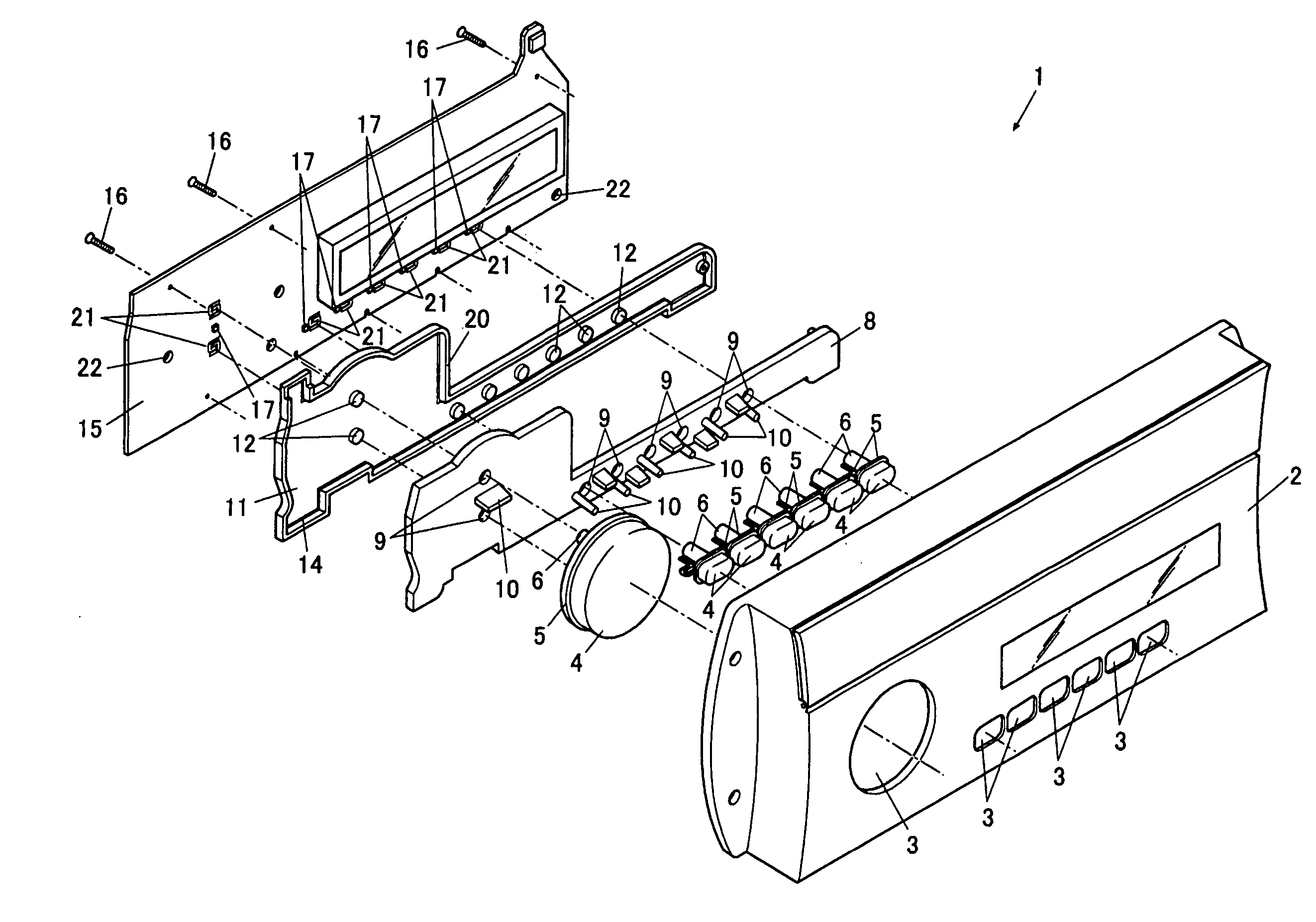
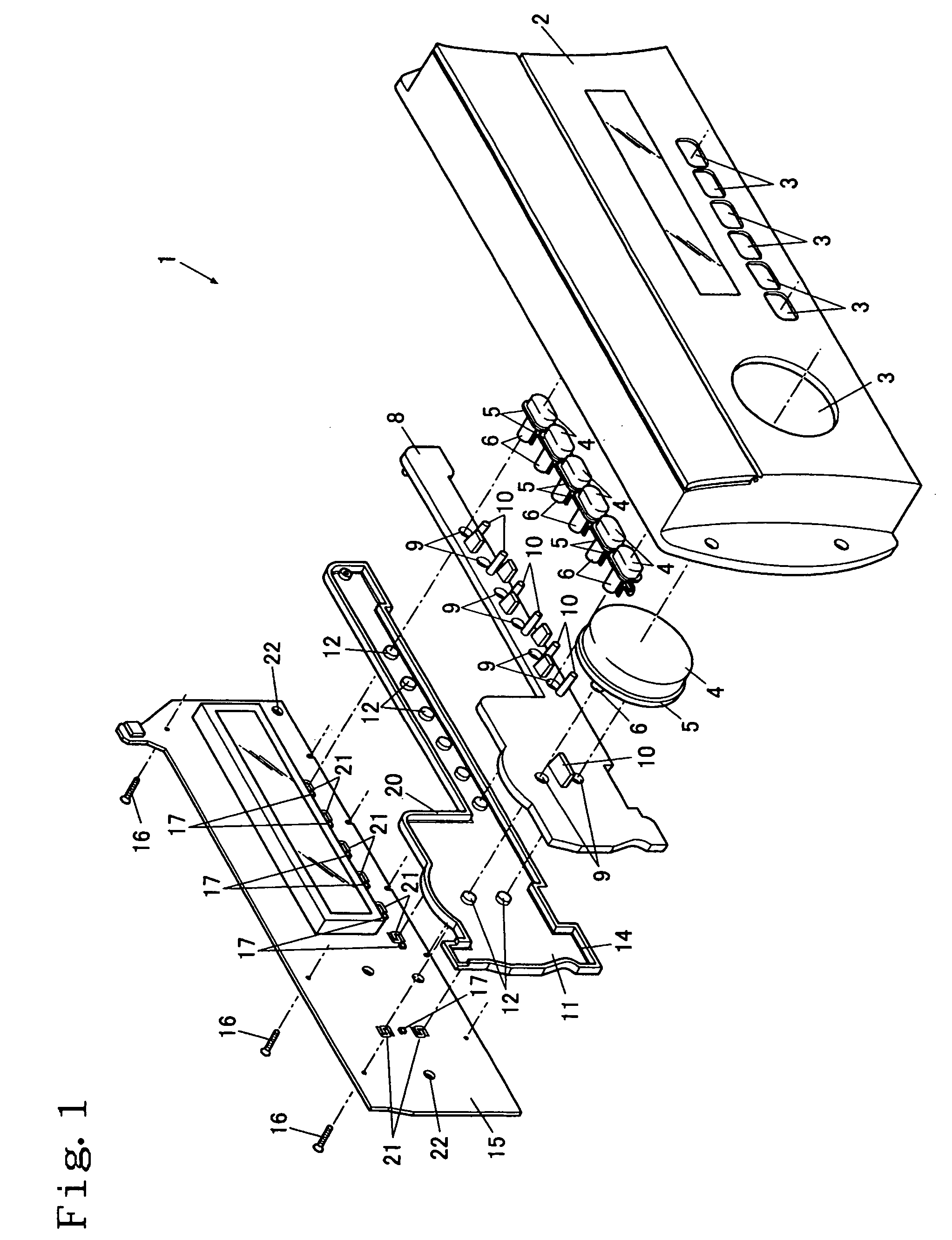
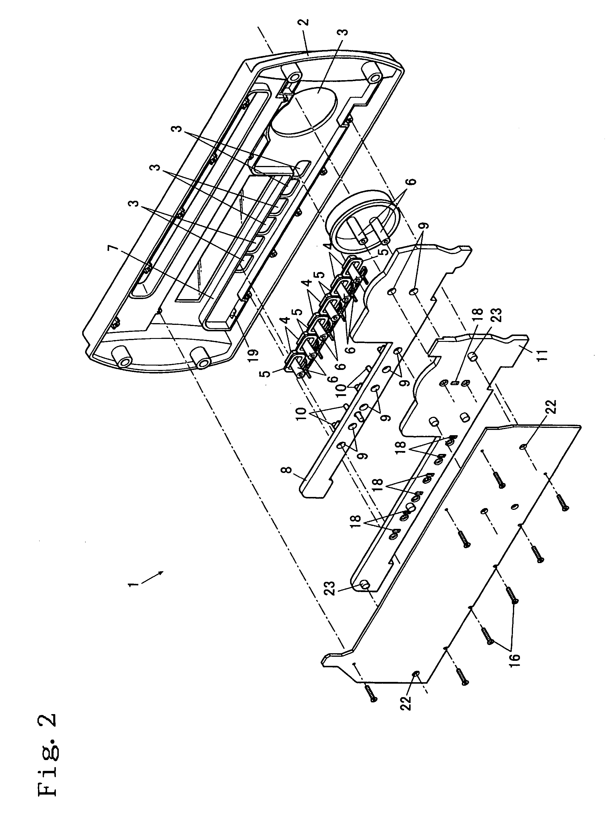
[0027]FIG. 1 is an exploded perspective view of a button waterproofing structure 1, viewed from the front, FIG. 2 is an exploded perspective view of a button waterproofing structure 1, viewed from the back, and FIG. 3 is a sectional view of a button waterproofing structure 1.

[0028] This button waterproofing structure 1 can be used for electronic equipment mounted on an instrument panel of a transporting means, such as a ship, yacht, boat, motorcycle, and car, and on a building wall surface of bathroom, toilet room, kitchen, and the like. The front of electronic equipment is covered with a box-shaped front panel 2, and the electronic equipment is mounted on the instrument panel or the wall so that the front panel 2 is exposed facing to the front.

[0029] Through the front panel 2, a plurality of button holes 3 penetrate from the front surface to the back surface, and buttons 4 are inserted in the button holes 3. The button 4 is formed into a cup shape such as to open at the rear, and...

second embodiment

[0049] A button waterproofing structure 1A in accordance with a second embodiment will be described with reference to FIG. 4. FIG. 4 is a sectional view of the button waterproofing structure 1A. In the description below, for the button waterproofing structure 1A, the same reference numerals are applied to elements that correspond to the elements of the button waterproofing structure 1 of the first embodiment.

[0050] The front-to-back thickness of the front panel 2 of this button waterproofing structure 1A is larger than the front-to-back thickness of the front panel 2 of the button waterproofing structure 1, and a concave portion 31 is formed in the back surface of the front panel 2. This concave portion 31 corresponds to the space 30 of the first embodiment. Therefore, the rib 7 as described in the first embodiment is not formed on the back surface of the front panel 2.

[0051] At the bottom of the concave portion 31, the plurality of button holes 3 (in FIG. 4, only one button hole ...

third embodiment

[0056] A button waterproofing structure 1B in accordance with a third embodiment will be described with reference to FIG. 5. FIG. 5 is a sectional view of the button waterproofing structure 1B. In the description below, for the button waterproofing structure 1B, the same reference numerals are applied to elements that correspond to the elements of the button waterproofing structure 1 of the first embodiment.

[0057] On the back surface of the front panel 2 of the button waterproofing structure 1B, the rib 7 as described in the first embodiment is not formed. On the other hand, as in the case of the first embodiment, the frame portion 20 is convexly provided in the front surface edge portion of the rubber sheet 11, and the front-side end portion of the frame portion 20 is in close contact with the front panel 2 so as to surround the plurality of button holes 3 (in FIG. 4, only one button hole 3 is shown). The circuit board 15 is installed with the screws 16, and by the fastening of th...


PUM


Abstract

Button holes 3 are formed in a front panel 2. Buttons 4 are arranged in the button holes 3, and a rib 7 convexly provided on the back surface of the front panel 2 surrounds the button holes 3. A light transmitting rubber sheet 11 closes a space 30 surrounded by the rib 7 and is held between a circuit board 15 and the rib 7. Contact portions 12 are provided on the rubber sheet 11 so as to be brought into contact with and separated from the circuit board 15 by the elastic force of the rubber sheet 11. Light emitting elements 17 are mounted on the circuit board 15 so as to correspond to the buttons 4, and are accommodated in accommodation concave portions 18 in the rubber sheet 11.

Description

BACKGROUND OF THE INVENTION [0001] 1. Field of the Invention [0002] The present invention relates to a button waterproofing structure. [0003] 2. Related Background Art [0004] On-vehicle audio equipment is provided with buttons for pushing operation on a front panel. Since the on-vehicle audio equipment is used by being installed in a cabin, it is generally designed so as not to be waterproof. In the case where the audio equipment of this type is mounted on a ship, yacht, boat, motorcycle, and the like, rainwater, seawater, etc. may intrude through a gap between the button and the front panel. Therefore, the intrusion of rainwater, seawater, etc. is prevented by covering the button with a rubber (for example, refer to Patent Document 1). [0005] Patent Document 1: Japanese Utility Model Application Laid-Open No. H3-28583 However, if the button is covered with a rubber, the design grade is low, and a sense of high class is lost. SUMMARY OF THE INVENTION [0006] Accordingly, an object of...

Claims


Application Information

Patent Timeline
IPC IPC(8): H01H9/04
CPCH01H9/18H01H13/86H01H2209/082H01H2223/004H01H2221/018H01H2223/002H01H2219/062
Inventor OHNISHI, TETSUSHI
Owner JVC KENWOOD CORP A CORP OF JAPAN
Why Eureka
Try Eureka