Electromagnetic relay

a technology of electromagnetic relays and relays, applied in the field of electromagnetic relays, can solve the problems of reducing current carrying capacity, occurrence of failure, increasing component counts, etc., and achieve the effect of long contact li

Active Publication Date: 2006-10-12
EM DEVICES CORP
View PDF30 Cites 13 Cited by
  • Summary
  • Abstract
  • Description
  • Claims
  • Application Information

AI Technical Summary

Benefits of technology

[0014] In view of the above, it is an object of the present invention to provide an electromagnetic relay which is capable of reliably decreasing a contact bounce at time of closing a contact without causing a decrease in current-carrying capability and an increase in component counts.
[0026] By configuring as above, the surface of the plate-shaped normally open fixed contact and the surface of the plate-shaped movable contact are opposed to each other in a manner to form a specified angle and, when the normally open fixed contact comes into surface-contact with the movable contact, after part of one contact portion comes into contact with part of other contact portion, the movable contact is twisted, while sliding on the plate-shaped movable contact due to elasticity of an arm-shaped spring member supporting the movable contact, which causes a residual portion of the contact to come into contact and causes repulsion at a time of collision to be reduced, thus preventing an occurrence of a contact bounce.
[0027] With the above configuration, the contact bounce at the time of closing the contact is reduced, which enables the provision of the electromagnetic relay to have a long contact life.

Problems solved by technology

If a contact bounce occurs in a state where a large amount of current is flowing, arc currents are produced and there is a danger of an occurrence of a failure such as welding of a contact or locking caused by a protrusion or hole formed on a contact surface.
As described above, in the Patent Reference 1, for example, in order to decrease the occurrence of arc currents, an electromagnetic relay is so configured that a fixed contact spring itself is made to have elasticity, however, to make the fixed contact member itself have elasticity, it is necessary to make a plate thickness be small, which causes a decrease in current-carrying capability due to reduction in a cross-sectional area for current carrying.
Moreover, if a vibration-isolating material is to be mounted thereon, new problems of an increase in component counts accompanied by an increase in the number of man-hours or in costs arise.

Method used


Image

  • Electromagnetic relay
  • Electromagnetic relay
  • Electromagnetic relay

Examples


first embodiment

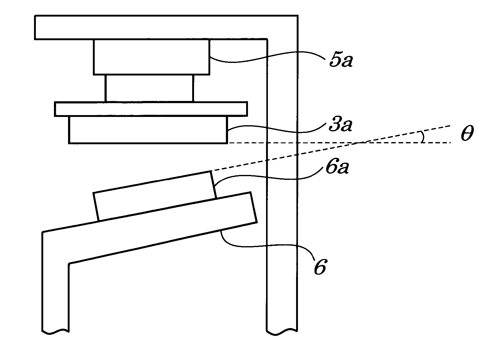
[0038]FIG. 4 is a side view of a contact portion when viewed from a direction to which a movable contact 3a slides on a normally open fixed contact 6a according to the first embodiment of the present invention. A normally open fixed contact 6a is inclined and an inclination angle θ is formed by a surface of the movable contact 3a and by a surface of the normally open fixed contact 6a. When a voltage is applied to a coil, the surface of the inclined normally open fixed contact 6a strikes the surface of the movable contact 3a to come into physical contact. At this time point, a movable contact spring 3 bends with attractive forces of magnetic, which causes the movable contact 3a and the normally open fixed contact 6a to slide relatively on each other, and which the movable contact 3a is attracted to the normally open fixed contact 6a.

[0039] An electrical life test under lamp-loaded conditions was conducted, using a testing circuit shown in FIG. 7, on an electromagnetic relay having i...

second embodiment

[0043]FIG. 5 is a diagram showing a side face of a contact portion when viewed from a direction to which a movable contact 3a slides on a normally open fixed contact 6a according to the second embodiment of the present invention. The movable contact 3a is inclined and an inclination angle θ is formed by a surface of the movable contact 3a and by a surface of a normally open fixed contact 6a. When a voltage is applied to a coil (not shown), the surface of the inclined movable contact 3a strikes the surface of the normally open fixed contact 6a to come into physical contact. At this time point, a movable contact spring 3 bends with attractive forces of magnetic, which causes the movable contact 3a to slide on the normally open fixed contact 6a, and which the movable contact 3a is attracted to the normally open fixed contact 6a.

[0044] An electrical life test under lamp-loaded conditions was conducted, using a testing circuit shown in FIG. 7, on the electromagnetic relay having its con...

third embodiment

[0046]FIG. 6 is a diagram showing a side face of a contact portion when viewed from a direction to which a movable contact 3a slides on a normally open fixed contact 6a according to a third embodiment of the present invention. On a normally open fixed contact 6a is formed an inclined surface being of a convex shape and having an inclination angle θ. When a voltage is applied to a coil (not shown), the surface of the inclined movable contact 3a strikes the surface of the inclined surface of the normally open fixed contact 6a to come into physical contact. At this time point, a movable contact spring 3 bends with attractive forces of magnetic, which causes the movable contact 3a and the normally open fixed contact 6a to slide relatively on each other, and which the movable contact 3a is attracted to the normally open fixed contact 6a.

[0047] An electrical life test under lamp-loaded conditions was conducted, using a testing circuit shown in FIG. 7, on an electromagnetic relay having i...


PUM


Abstract

An electromagnetic relay is provided which is capable of reducing a contact bounce at time of closing a contact. The electromagnetic relay is so configured that an opposed angle θ is 0°<θ<45°, when viewed from a direction to which a normally open fixed contact and a movable contact slide before the normally open fixed contact comes into surface-contact with the movable contact spring.

Description

BACKGROUND OF THE INVENTION [0001] 1. Field of the Invention [0002] The present invention relates to an electromagnetic relay and more particularly to the electromagnetic relay to be used as a vehicle-mounted electromagnetic relay or a like. [0003] The present application claims priority of Japanese Patent Application No. 2005-114584 filed on Apr. 12, 2005, which is hereby incorporated by reference. [0004] 2. Description of the Related Art [0005] Conventionally, an electromagnetic relay is used for electrical components of automobiles or a like. The general and conventional electromagnetic relay being used as a vehicle-mounted one is described below. [0006]FIG. 1 is a perspective view showing configurations of a conventional electromagnetic relay 10. FIG. 2 is partially exploded perspective view showing configurations of the conventional electromagnetic relay 10 of FIG. 1. FIG. 3 is a partial side view showing configurations of the conventional electromagnetic relay 10 of FIG. 1. As...

Claims


Application Information

Patent Timeline
Patent Type & Authority Applications(United States)
IPC IPC(8): H01H51/22
CPCH01H1/18H01H50/54H01H1/50H01H1/2083H01H1/12
Inventor KON, HIROYUKIMORIMOTO, MASAYUKI
Owner EM DEVICES CORP
Why Eureka
Try Eureka