
Zoom lens and imaging apparatus including the same

Active Publication Date: 2006-10-12
CANON KK
View PDF15 Cites 10 Cited by
  • Summary
  • Abstract
  • Description
  • Claims
  • Application Information

AI Technical Summary

Benefits of technology

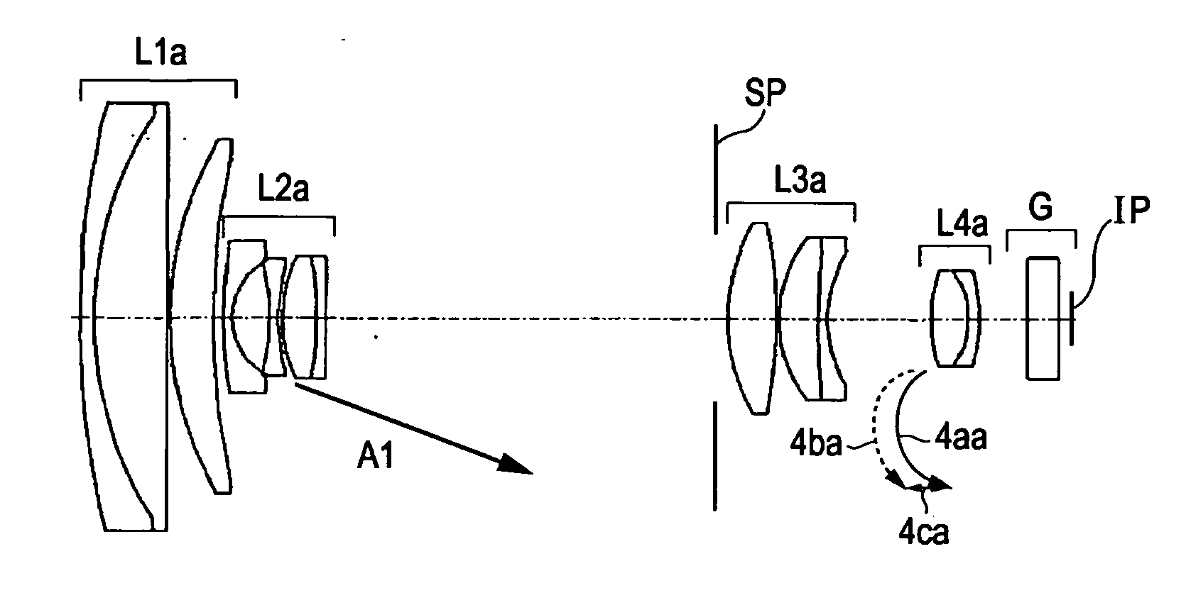
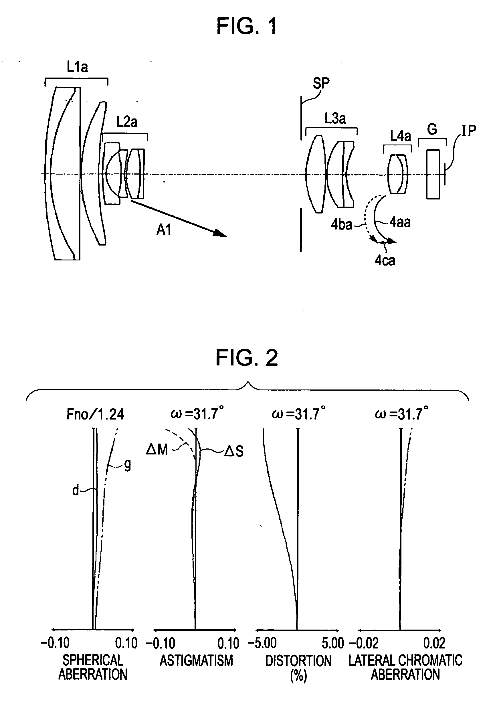
[0015] Accordingly, at least-one exemplary embodiment is directed to compact zoom lenses having high zoom ratio and also high optical performance over the whole zoom range achieved by appropriately setting the refracting powers of the lens groups and the configurations of the lens groups and provides imaging apparatuses including the same.

Problems solved by technology

In Japanese Patent Laid-Open No. 05-027167, chromatic aberration may not be sufficiently corrected since the fourth lens group includes only one positive lens.
Therefore, a zoom ratio up to 8 times causes no problem, but a zoom ratio higher than or equal to 20 times can lead to large fluctuations of the chromatic aberration during focusing adjacent to the telescopic end.
As in the case of Japanese Patent Laid-Open No. 05-027167, the fourth lens group includes only one positive lens in U.S. Pat. No. 6441968, and thus the chromatic aberration may not be sufficiently corrected.
Therefore, when the brightness at a wide-angle end is higher than F1.8, optical performance at the wide-angle end becomes more difficult to be retained satisfactorily.
Furthermore, the external diameters of the lenses can become large with the aperture ratio, and the thicknesses of the lenses in the centers can be increased as the curvature radii of the positive lenses become small for ensuring the thicknesses of the lenses in the outer portions, resulting in an increment in size of the whole lens system.
However, when the refracting powers of the lens groups are merely enhanced without appropriately setting the configurations of the lens groups, aberration fluctuation during zooming becomes large, thus making it difficult to achieve excellent optical performance over the whole variable-power range when high variable power is required.

Method used


Image

  • Zoom lens and imaging apparatus including the same
  • Zoom lens and imaging apparatus including the same
  • Zoom lens and imaging apparatus including the same

Examples


Embodiment Construction

[0032] The following description of at least one exemplary embodiment is merely illustrative in nature and is in no way intended to limit the invention, its application, or uses.

[0033] Processes, techniques, apparatus, and materials as known by one of ordinary skill in the relevant art may not be discussed in detail but are intended to be part of the enabling description where appropriate, for example the fabrication of the lens elements and their materials.

[0034] In all of the examples illustrated and discussed herein any specific values, for example the zoom ratio and F number, should be interpreted to be illustrative only and non limiting. Thus, other examples of the exemplary embodiments could have different values.

[0035] Notice that similar reference numerals and letters refer to similar items in the following figures, and thus once an item is defined in one figure, it may not be discussed for following figures.

[0036] Exemplary embodiments of a zoom lens and an imaging appa...


PUM


Abstract

At least one exemplary embodiment is directed to a zoom lens which includes a first lens group, which can have a positive refracting power; a second lens group, which can have a negative refracting power, and can move during zooming; a third lens group, which can have a positive refracting power; and a fourth lens group, which can have a positive refracting power, and can move during zooming, the lens groups being aligned in order from front to back, where the focal lengths fw and ft of the whole system at a wide-angle end and at a telescopic end, respectively, can satisfy the following conditions: 0.15<fw / f4<0.26 1.0<f3 / (fw·ft)1 / 2<1.2.

Description

BACKGROUND OF THE INVENTION [0001] 1. Field of the Invention [0002] The present invention relates to zoom lenses, more particularly, though not exclusively, the present invention relates to zoom lenses that can be used as image-taking lenses in imaging apparatuses. [0003] 2. Description of the Related Art [0004] In optical imaging systems used for imaging apparatuses such as video cameras using solid-state image-pickup devices, digital still cameras, and silver-salt film cameras using silver-salt films, the desirability of compact-system zoom lenses having optical performance of high resolution have increased. [0005] Since video cameras capable of recording still images of high definition have also been increasingly required, the desirability of lens systems that are compact yet having high-optical performance have increased. [0006] One such zoom lens system that can be used includes four lens groups consisting of a first lens group having a positive refracting power, a second lens ...

Claims


Application Information

Patent Timeline
IPC IPC(8): G02B15/14
CPCG02B15/173G02B15/144113
Inventor MIYAZAWA, NOBUYUKI
Owner CANON KK
Learn More