
Switch assembly

a technology of switch assembly and pivot contact plate, which is applied in the direction of contact, electrical apparatus, redundant contact pair, etc., can solve the problems of burning or melting the pivot contact plate, the contact between the pivot contact lever and the support on the pivot point may not be very desirable, and the heating generation and “int” problem

Active Publication Date: 2006-10-26
SHANGHAI BAICHENG ELECTRONICS
View PDF32 Cites 12 Cited by
  • Summary
  • Abstract
  • Description
  • Claims
  • Application Information

AI Technical Summary

Benefits of technology

[0013] The improved features and advantageous effects of the present invention, which will now be described by way of example only with reference to the accompanying drawings, will be more clearly and completely understood by a skilled person in the art.

Problems solved by technology

However, contact between the pivot contact lever and the support on the pivot point may be not very desirable because it generates a high contact resistance and causes the heating generation and “INT” problem.
The INT problem refers to the sparkle that is generated at the contact point due to unstable contact at the contact point under the normal working condition and / or environment.
The sparkle, in return, may burn or melt the pivot contact plate, which becomes a more serious problem on a high rating switch.
In addition, the above-mentioned conventional switches have the following deficiency.
Thus, even though contact loss is very small for the second pivot contact lever, heat is generated in such a high current situation.
A conventional switch has further deficiency in that a conventional switch is normally provided with a forward / reverse switch mechanism that is able to alternate the pole of the output voltage.
However, such a structure does not effectively minimize heat generation.

Method used


Image

  • Switch assembly
  • Switch assembly
  • Switch assembly

Examples


Embodiment Construction

[0081] Referring to the drawings, there is shown in detail a switch assembly, which is a high rating DC switch assembly, according to a preferred embodiment of the present invention. The present invention can be applied to a normal switch but is more useful when used for a high rating DC switch assembly.

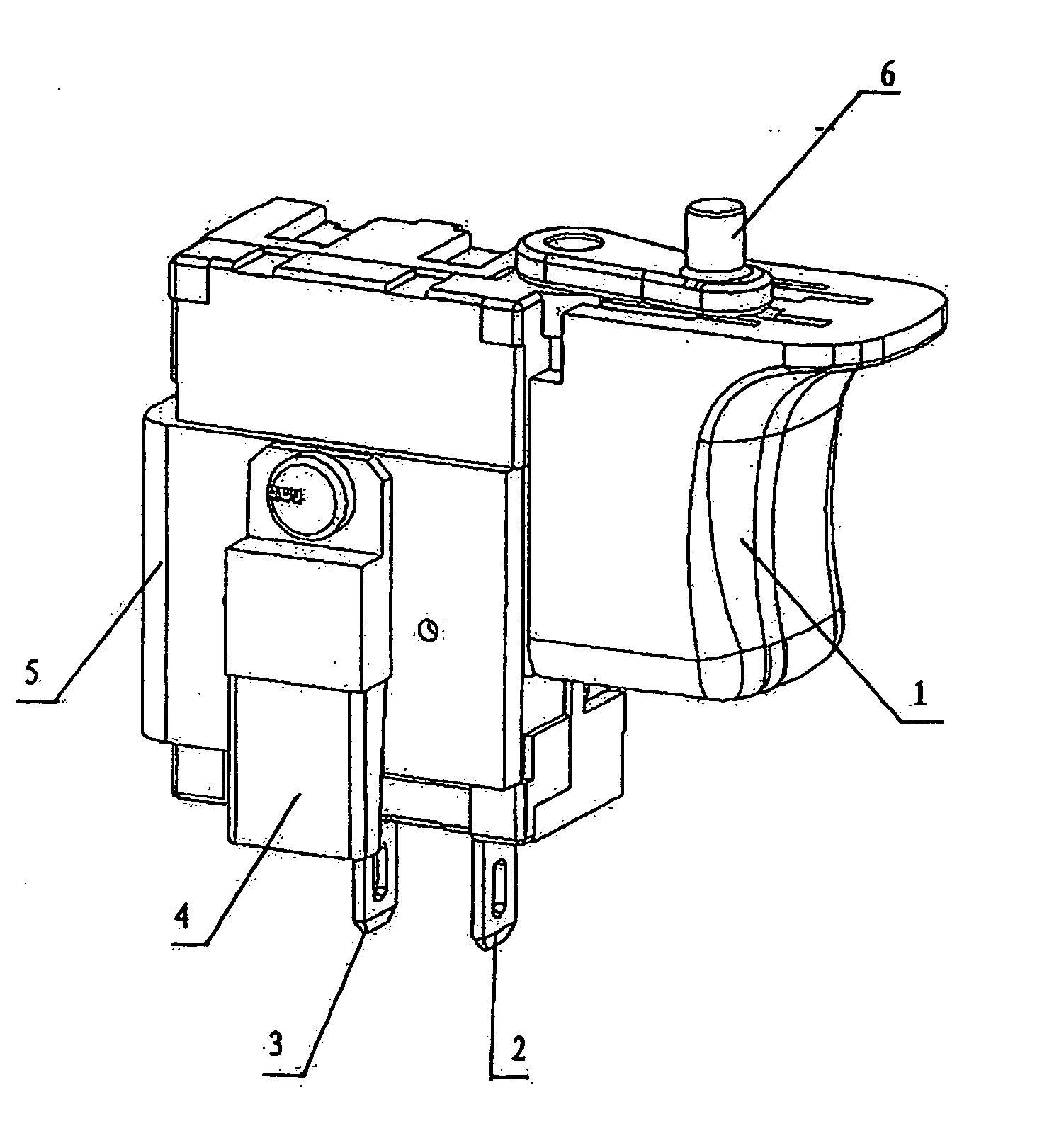
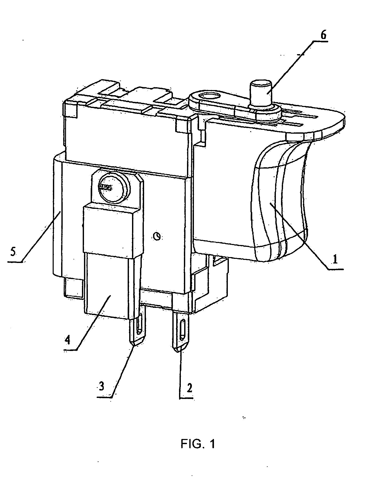
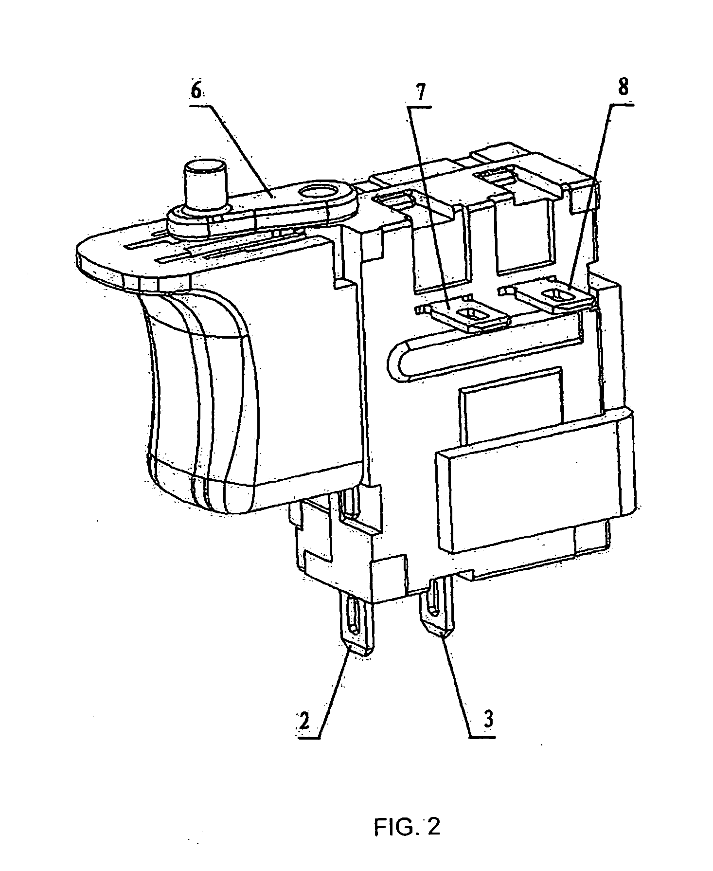
[0082] As shown in FIGS. 1 and 2, the switch assembly is seen externally to comprise a casing, a trigger 1, first and second input ports 2, 3 used for connection to the positive or negative pole of a supply of an electric voltage, for example, a battery, first and second external output ports 7, 8 used for connection to ports of an electricity consuming device to be controlled by said switch assembly, for example, an electric tool having an electric motor output ports, an MOSFET 4 used as a solid state switch, a heat sink 5, and a forward / reverse lever 6. The trigger is under the control of a user. The switch assembly is open when the trigger 1 is in the outermost position. The swit...


PUM


Abstract

A switch assembly provides a pressing plate on a pivot contact lever to minimize heat generation at the point between the pivot contact lever and the contact point by providing an additional parallel connection contact plate which is in parallel connection to the pivot contact lever. The switch assembly provides convex contact portions on the internal output ports of the forward / reverse switch mechanism. A supplementary elastic metal plate to the pivot contact lever is provided to solve the problem of loose contact at the pivot connection site where the pivot contact lever and the support unit meet, and provides a supplementary contact unit to the movable contact device at the forward / reverse switch mechanism.

Description

BACKGROUND [0001] The present invention relates to an electrical switch, particularly to a high power DC switch, more particularly to a trigger switch used for trigger control of a power tool. [0002] It is publicly known in the art that there is a Marquardt (trademark) 2711.5507 high rating DC switch powered with electricity of 18V DC 25 A. U.S. Pat. No. 6,717,080 discloses a trigger switch assembly used for an electric power tool having an electric motor. U.S. Pat. No. 6,741,051 discloses a trigger controller used for an electric power tool including an electric motor. Also, U.S. Pat. No. 6,104,105 discloses an electrical switch for switching on and off a tool having an electric motor. [0003] A pivot contact lever mechanism is used in all of the above-mentioned switches to switch on and switch off the electric connection. Typically, one end of the pivot contact lever is pivotably attached to a support which is connected to an input terminal for electric current. An output terminal ...

Claims


Application Information

Patent Timeline
Patent Type & Authority Applications(United States)
IPC IPC(8): H01H13/02
CPCH01H1/5833H01H9/061H01H9/063H01H2001/0005H01H9/52H01H13/08H01H9/40
Inventor XU, XINSHENG
Owner SHANGHAI BAICHENG ELECTRONICS
Learn More