Eureka AIR delivers breakthrough ideas for toughest innovation challenges, trusted by R&D personnel around the world.

Rollers separating unit and image forming apparatus having the same

a separation unit and separation unit technology, applied in the field of separation unit and image forming apparatus, can solve the problems of increasing the possibility that the transferred paper may be jammed, the jammed paper is not easily removed, and the user may not be able to easily remove the jammed paper, so as to achieve the effect of easy removal of jammed paper

Active Publication Date: 2006-10-26
HEWLETT PACKARD DEV CO LP
View PDF8 Cites 21 Cited by
  • Summary
  • Abstract
  • Description
  • Claims
  • Application Information

AI Technical Summary

Benefits of technology

[0008] Accordingly, an aspect of the present invention provides a rollers separating unit which allows the user to easily remove jammed paper by releasing pressure of a fixing unit when the user opens a side cover of an image forming apparatus, as well as an image forming apparatus having the same installed therein.
[0016] According to another aspect of the invention, there is provided a rollers separating unit including: a pair of elastic support members rotatably hinge-coupled to both sides of a housing of a fixing unit, to elastically support a pressurizing roller to pressurize a heating roller; a pair of first levers rotatably hinge-coupled to one end of the pair of elastic support members, to rotate the pair of elastic support members at a predetermined angle so that the heating roller and the pressurizing roller are separated from each other; and a side cover rotatably hinge-coupled to one side of a main body, to increase a distance between the heating roller and the pressurizing roller by operating the pair of first levers.
[0019] According to yet another aspect of the invention, there is provided an image forming apparatus having a rollers separating unit including: a pair of elastic support members rotatably hinge-coupled to both sides of a housing of a fixing unit, to elastically support a pressurizing roller to pressurize a heating roller; a pair of first levers rotatably hinge-coupled to one end of the pair of elastic support members, to rotate the pair of elastic support members at a predetermined angle so that the heating roller and the pressurizing roller are separated from each other; and a side cover rotatably hinge-coupled to one side of a main body, to increase a distance between the heating roller and the pressurizing roller by operating the pair of first levers.
[0020] As is described above, in the rollers separating unit of the present invention, when the side cover of the image forming apparatus is opened, the pressurizing roller and the heating roller are separated from each other, to release pressure of the fixing unit. Therefore, the user may relatively easily remove jammed paper.
[0021] In addition, in the image forming apparatus having the rollers separating unit, the pressurizing roller and the heating roller are separated from each other simply by opening / closing the side cover. As a result, the user may relatively easily remove jammed paper.

Problems solved by technology

In general, in an image forming apparatus, transferring a printing medium on which an image is formed such as paper (hereinafter, referred to as ‘paper’) and forming an image on the paper increases the possibility that the transferred paper may be jammed.
However, when the paper passing through the fixing unit is jammed between the pressurizing roller and the heating roller, since the pressurizing roller pressurizes the paper to the heating roller, the jammed paper is not easily removed.
As a result, the user may not easily remove the jammed paper and either the heating roller or the pressurizing roller may be damaged.

Method used


Image

  • Rollers separating unit and image forming apparatus having the same
  • Rollers separating unit and image forming apparatus having the same
  • Rollers separating unit and image forming apparatus having the same

Examples


Embodiment Construction

[0032] Reference will now be made in detail to the present embodiments of the present invention, examples of which are illustrated in the accompanying drawings, wherein like reference numerals refer to the like elements throughout. The embodiments are described below in order to explain the present invention by referring to the figures.

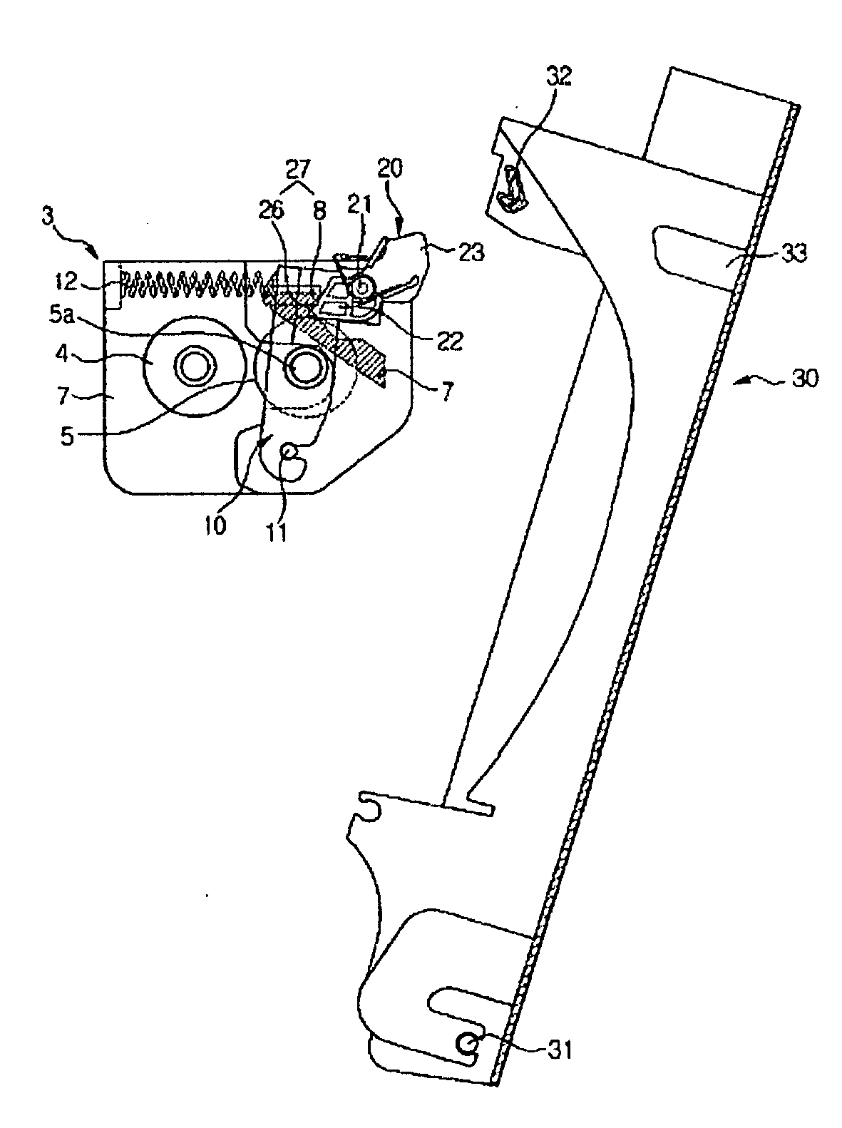
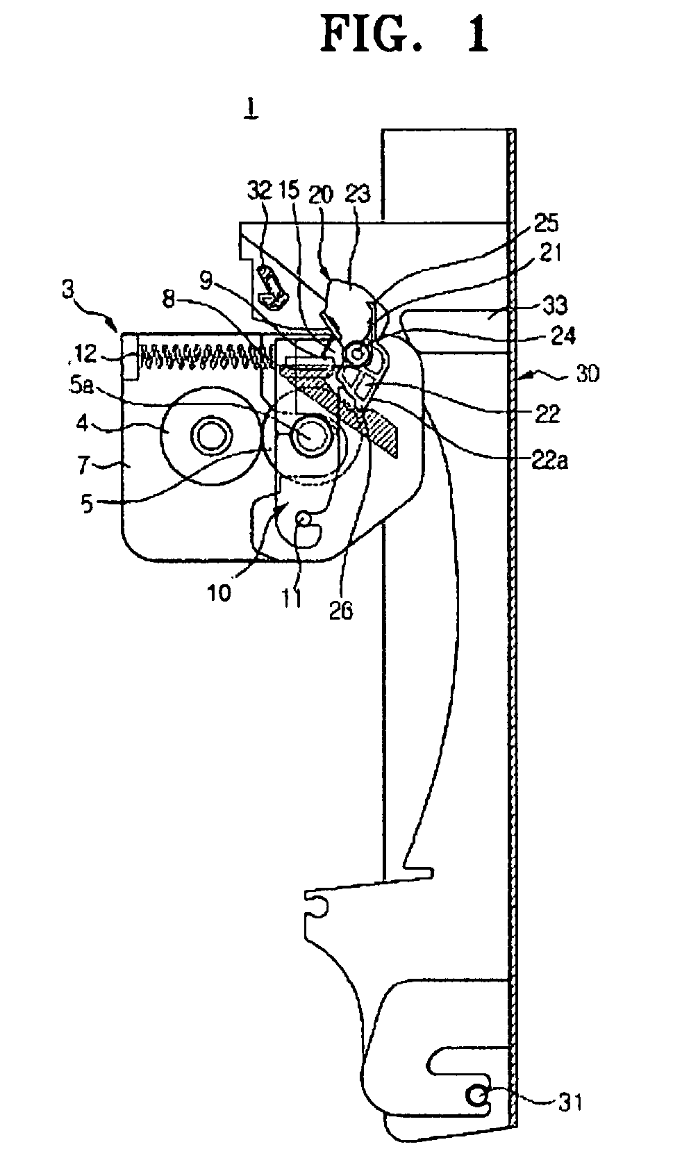
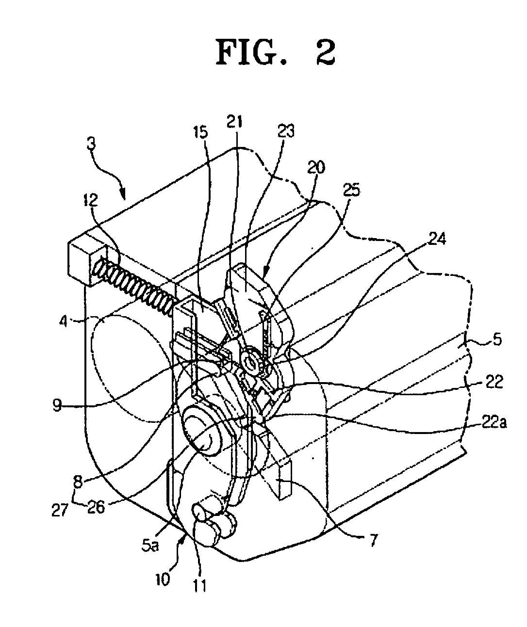
[0033] Referring to FIGS. 1 and 2, the rollers separating unit 1 is installed in a fixing unit 3, and includes an elastic support member 10, a first lever 20 and a side cover 30.

[0034] The fixing unit 3 is installed in a main body 101 (refer to FIG. 7) of the image forming apparatus, and includes a heating roller 4 to generate heat, a pressurizing roller 5 to pressurize the heating roller 4, and a housing 7 to house the heating roller 4 and the pressurizing roller 5.

[0035] The elastic support member 10 is rotatably hinge-coupled to one side of the housing 7 of the fixing unit 3. That is, the bottom end of the elastic support member 10 is installed ...


PUM


Abstract

A rollers separating unit which controls a distance between a heating roller and a pressurizing roller of a fixing unit by an opening / closing of a side cover. The rollers separating unit includes an elastic support member rotatably hinge-coupled to one side of a housing of a fixing unit, to elastically support a roller installed at an outer portion of a main body between a pair of rollers so that the pair of rollers pressurize each other, a first lever rotatably hinge-coupled to one end of the elastic support member, to rotate the elastic support member at a first predetermined angle so that the pair of rollers are separated from each other, and a side cover rotatably hinge-coupled to one side of the main body, to increase a distance between the pair of rollers by operating the first lever.

Description

CROSS-REFERENCE TO RELATED APPLICATIONS [0001] This application claims the benefit of Korean Application No. 2005-32814, filed Apr. 20, 2005, in the Korean Intellectual Property Office, the disclosure of which is incorporated herein by reference. BACKGROUND OF THE INVENTION [0002] 1. Field of the Invention [0003] An aspect of the present invention relates to an image forming apparatus, and, more particularly, to a rollers separating unit which may separate a heating roller from a pressurizing roller to remove paper jammed in a fixing unit of an image forming apparatus, as well as an image forming apparatus having the same installed therein. [0004] 2. Description of the Related Art [0005] In general, in an image forming apparatus, transferring a printing medium on which an image is formed such as paper (hereinafter, referred to as ‘paper’) and forming an image on the paper increases the possibility that the transferred paper may be jammed. [0006] In particular, an electrophotographic...

Claims


Application Information

Patent Timeline
Patent Type & Authority Applications(United States)
IPC IPC(8): G03G15/20G03G21/00
CPCG03G15/2035
Inventor LEE, BONG-HEELIM, HO-MIN
Owner HEWLETT PACKARD DEV CO LP
Why Eureka
Eureka Blog
Learn More