

Mask apparatus
a mask and mask technology, applied in the field of masks, can solve the problem that no prior art patents teach the use of woven fabric masks, and achieve the effect of enhancing the wearer's ability to s
- Summary
- Abstract
- Description
- Claims
- Application Information
AI Technical Summary
Benefits of technology
Problems solved by technology
Method used
Image

Examples
Embodiment Construction
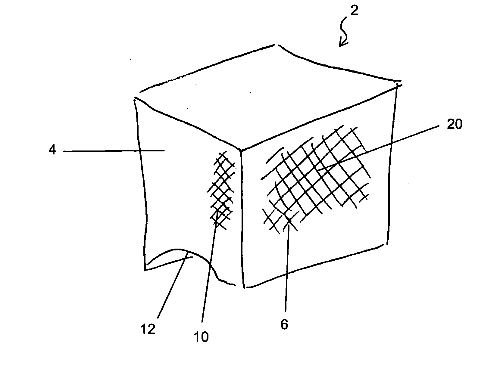
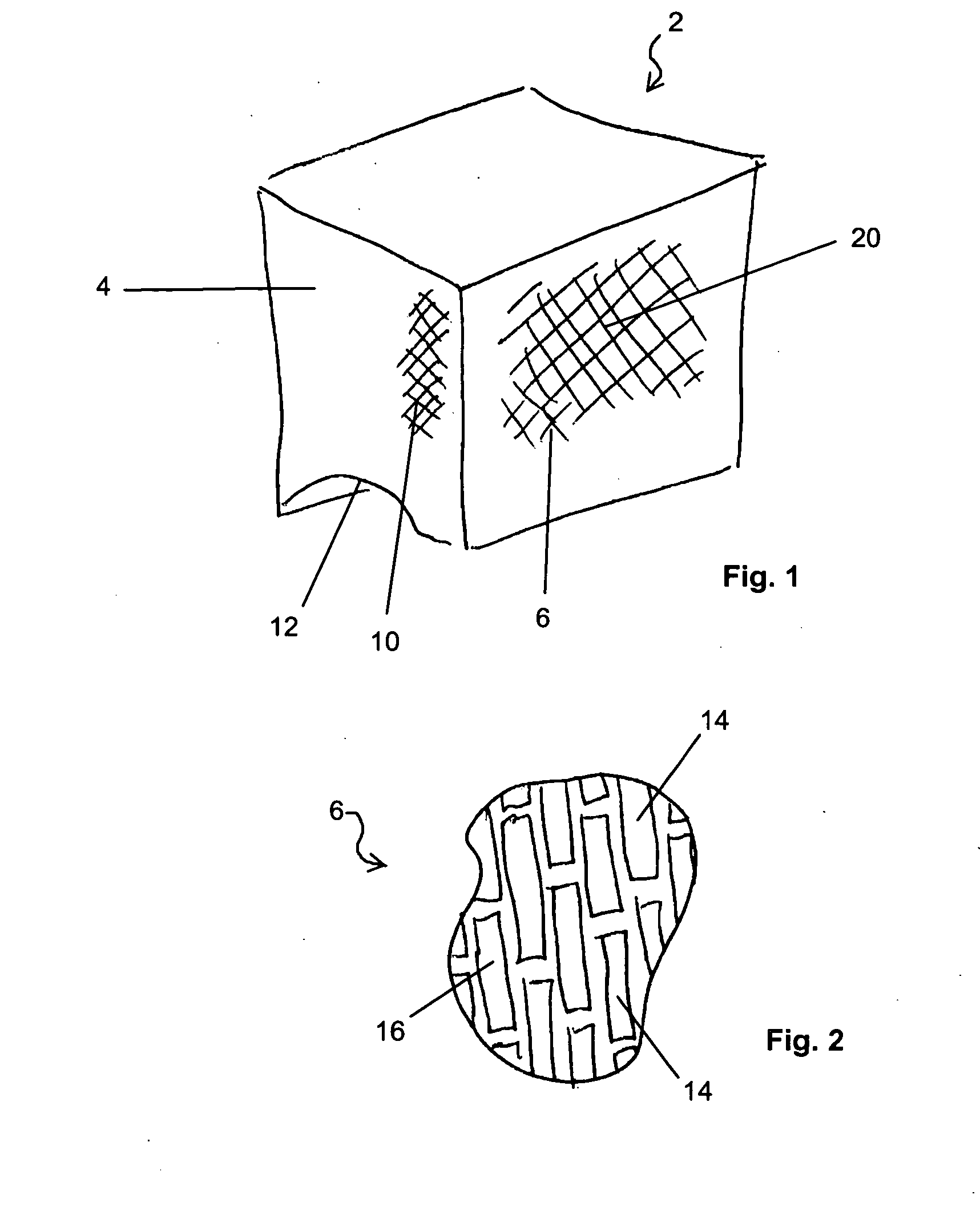
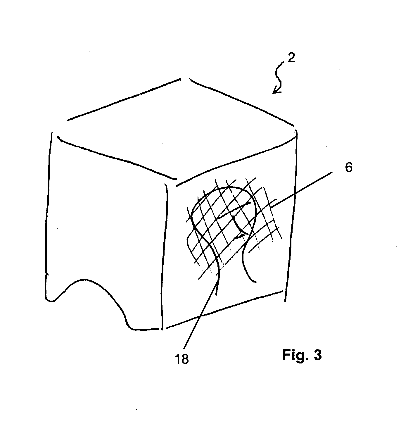
[0032] The mask 2 of the Invention is illustrated by FIG. 1. A mask body 4 is composed of paper and is shaped like a paper bag. The mask body 4 is adapted to cover the entire head of the wearer. A perforated panel 6 appears on the mask body 4. When the mask body 4 is in place and covering the head of the wearer, the perforated panel 6 is supported by the mask body 4 before the eyes 8 of the wearer as shown by FIG. 4. A perforated side panel 10 may be provided in the mask body 4 to provide peripheral vision to the wearer, to avoid a feeling of enclosure on the part of the wearer and to improve ventilation to the wearer. Cutouts 12 may be provided to allow the mask 2 of the Invention to better fit the shoulders of the wearer.
[0033]FIG. 2 is a magnified detail of an area of the perforated panel 6. The perforations 14 are cut, punched, burned or otherwise formed in the perforated panel 6. The perforated panel 6 may be separately formed from the mask body 4. Alternatively, the perforate...
PUM
 Abstract
Description
Claims
Application Information