Method and apparatus for shifting speeds in a fluid-actuated motor

a technology of fluid-actuated motors and shifting speeds, which is applied in the direction of bends, sealing/packing, and borehole/well accessories to achieve the effect of changing the rotational speed of the drill bi

Active Publication Date: 2006-11-02
NAT OILWELL DHT
View PDF7 Cites 103 Cited by
  • Summary
  • Abstract
  • Description
  • Claims
  • Application Information

AI Technical Summary

Benefits of technology

[0007] The present invention allows an operator to change the rotational speed of the drill bit by causing a portion of the fluid that is pumped through the drill string to bypass that part of the power section of a motor that imparts rotational motion on the drill bit without passing any of the fluid outside of the drill string. This is accomplished by means of a bypass valve installed inside, above, or below the power section of the motor.

Problems solved by technology

In underbalanced drilling, the fluid pumped down the drill string is composed of a mixture of fluid and gas.

Method used


Image

  • Method and apparatus for shifting speeds in a fluid-actuated motor
  • Method and apparatus for shifting speeds in a fluid-actuated motor
  • Method and apparatus for shifting speeds in a fluid-actuated motor

Examples


Embodiment Construction

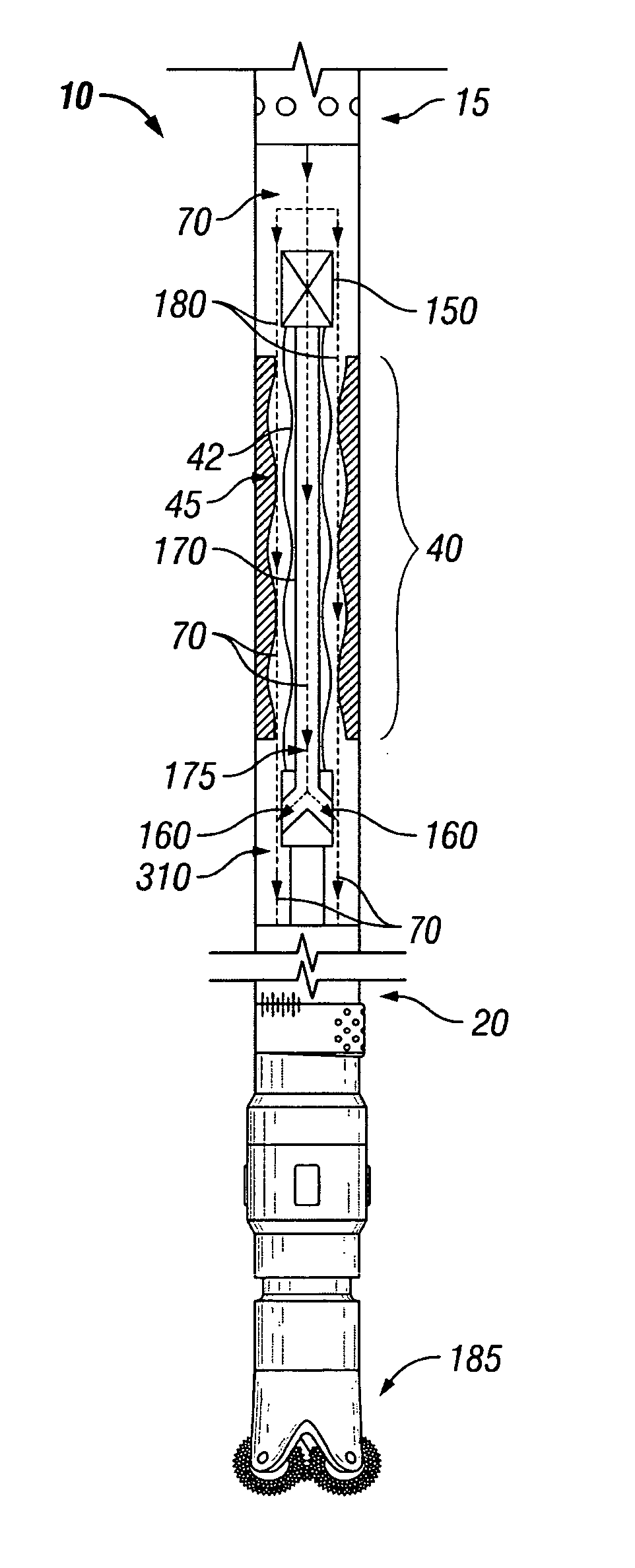
[0035]FIG. 1 is a diagram of an exemplary embodiment of a typical positive displacement motor 10 (“PDM”), or mud motor. The top side 15 of the motor connects to a drill string (not shown). The bottom side 20 connects to a drill bit 185. The power section 40 comprises a rotor 42 and stator 45. When a mud pump is turned on, fluid 70 enters the drill string, flows through the power section 40 and exits the bottom side 20 of the motor.

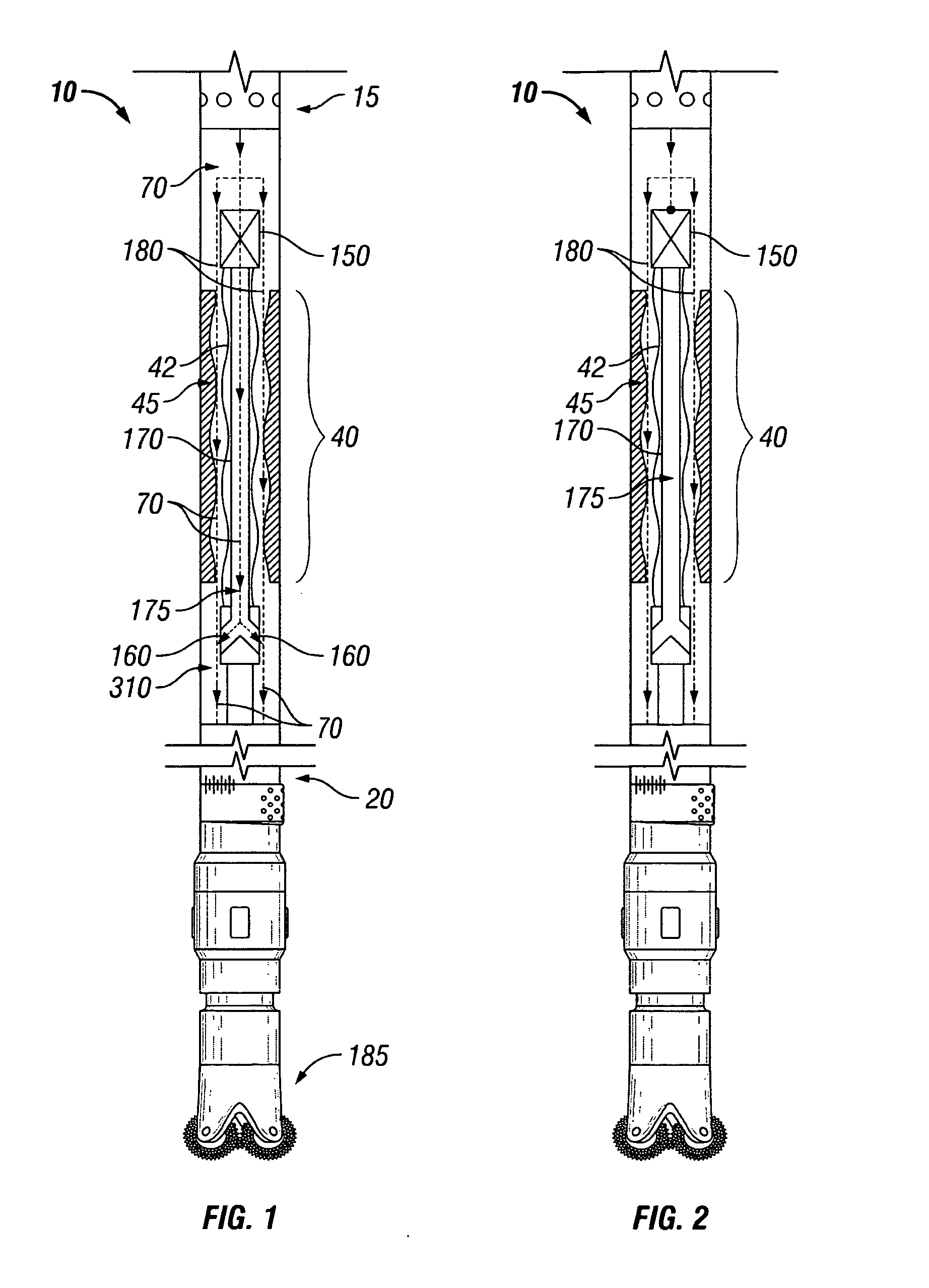
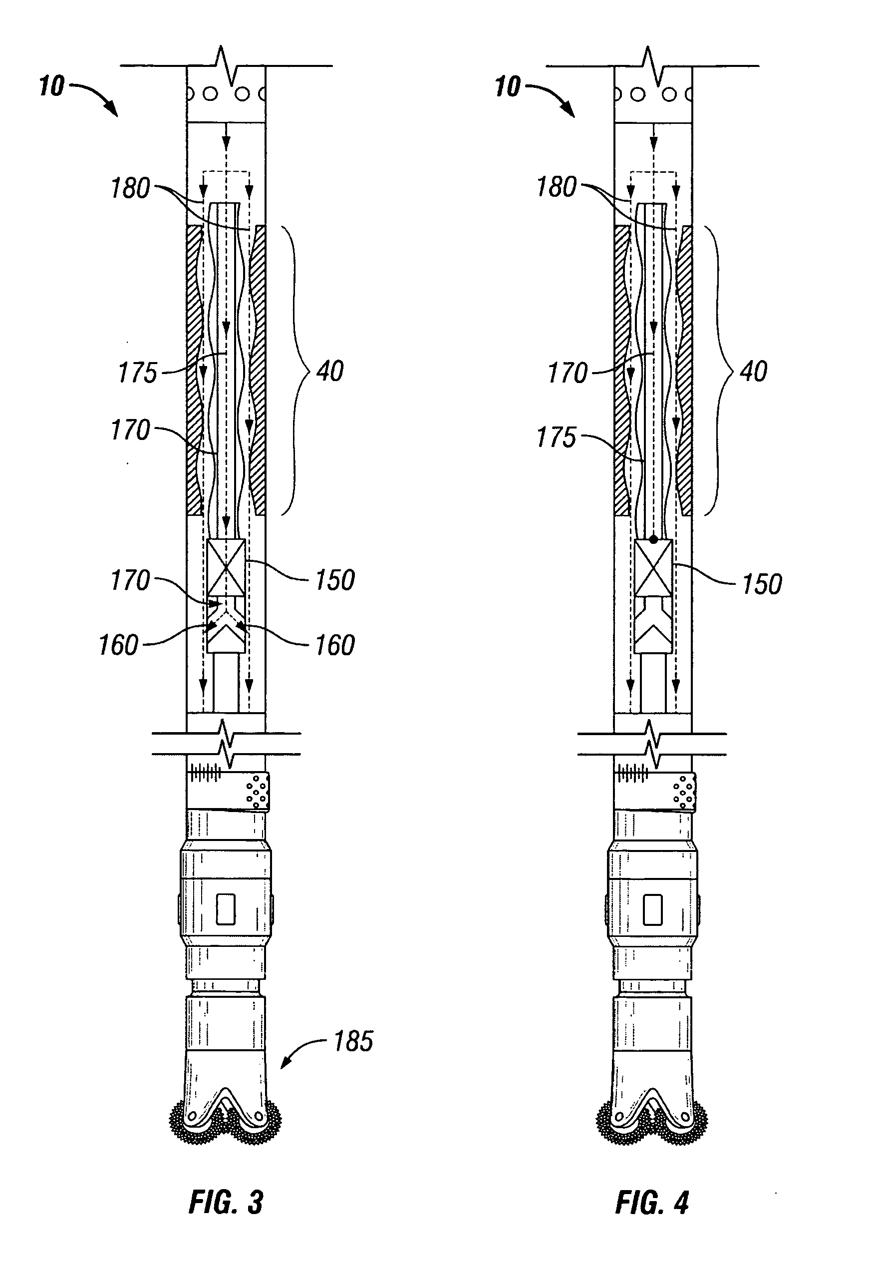
[0036]FIG. 2 is a diagram of an exemplary embodiment of a typical positive displacement motor 10 having a bypass valve 150 attached above the power section 40 of the motor 10; FIGS. 3 and 4 show the bypass valve 150 attached below the power section 40 of the motor 10; and FIGS. 5 and 6 show the bypass valve 150 attached inside the power section 40 of the motor. Because operation of the bypass valve is similar regardless of whether it attaches above, below, or inside the power section of a motor, only the operation of the bypass valve of FIGS. 1 and 2 need...


PUM


Abstract

A method and apparatus for changing the speed of a drill bit down hole in a fluid-actuated motor, including a positive displacement motor and a hydraulic motor, is disclosed. The apparatus comprises a bypass valve installed in the motor for controlling flow through and around the power section of the motor. When closed, the bypass valve forces all fluid to flow through the power section of the motor, imparting maximum speed to the drill bit. When opened, a portion of the fluid flow is allowed to flow around the power section of the motor, thereby reducing the speed of the drill bit. The bypass valve may be opened or closed mechanically, electrically, hydraulically, pneumatically, or by any other means, including a removable plug.

Description

FIELD OF THE INVENTION [0001] The present invention generally relates to fluid-actuated motors, including positive displacement motors, known as Moineau pump-type drilling motors, and hydraulic motors, and specifically to a fluid-actuated motor having a variable rotor bypass valve installed therein to alter the rotational speed of the drill bit without the need for the motor to be removed from the well. BACKGROUND OF THE INVENTION [0002] In the oil drilling industry, there are two traditional methods of drilling an oil well. One is to attach a drill bit at the end of a drill string, apply downward pressure, and rotate the drill string from the surface so that the drill bit cuts into a formation. The problem with this method is that as the hole becomes deeper and the drill string becomes longer, the frictional forces due to the rotation of the drill string down hole increase, especially in deviated and horizontal wells. [0003] The second method is to place a motor down hole near the ...

Claims


Application Information

Patent Timeline
Patent Type & Authority Applications(United States)
IPC IPC(8): E21B4/00
CPCE21B4/02F03C2/08Y10S415/903F04C14/26F04C14/08Y10T137/2663Y10T137/2693Y10T137/4658
Inventor EL-RAYES, KOSAY I.SHWETS, PETER J.MELHAM, NAZEEH
Owner NAT OILWELL DHT
Why Eureka
Try Eureka