Method and apparatus for shifting speeds in a fluid-actuated motor

a technology of fluid-actuated motors and shifting speeds, which is applied in the direction of bends, instruments, borehole/well accessories, etc., to achieve the effect of changing the rotational speed of the drill bi

Active Publication Date: 2009-04-28
NAT OILWELL DHT
View PDF7 Cites 36 Cited by
  • Summary
  • Abstract
  • Description
  • Claims
  • Application Information

AI Technical Summary

Benefits of technology

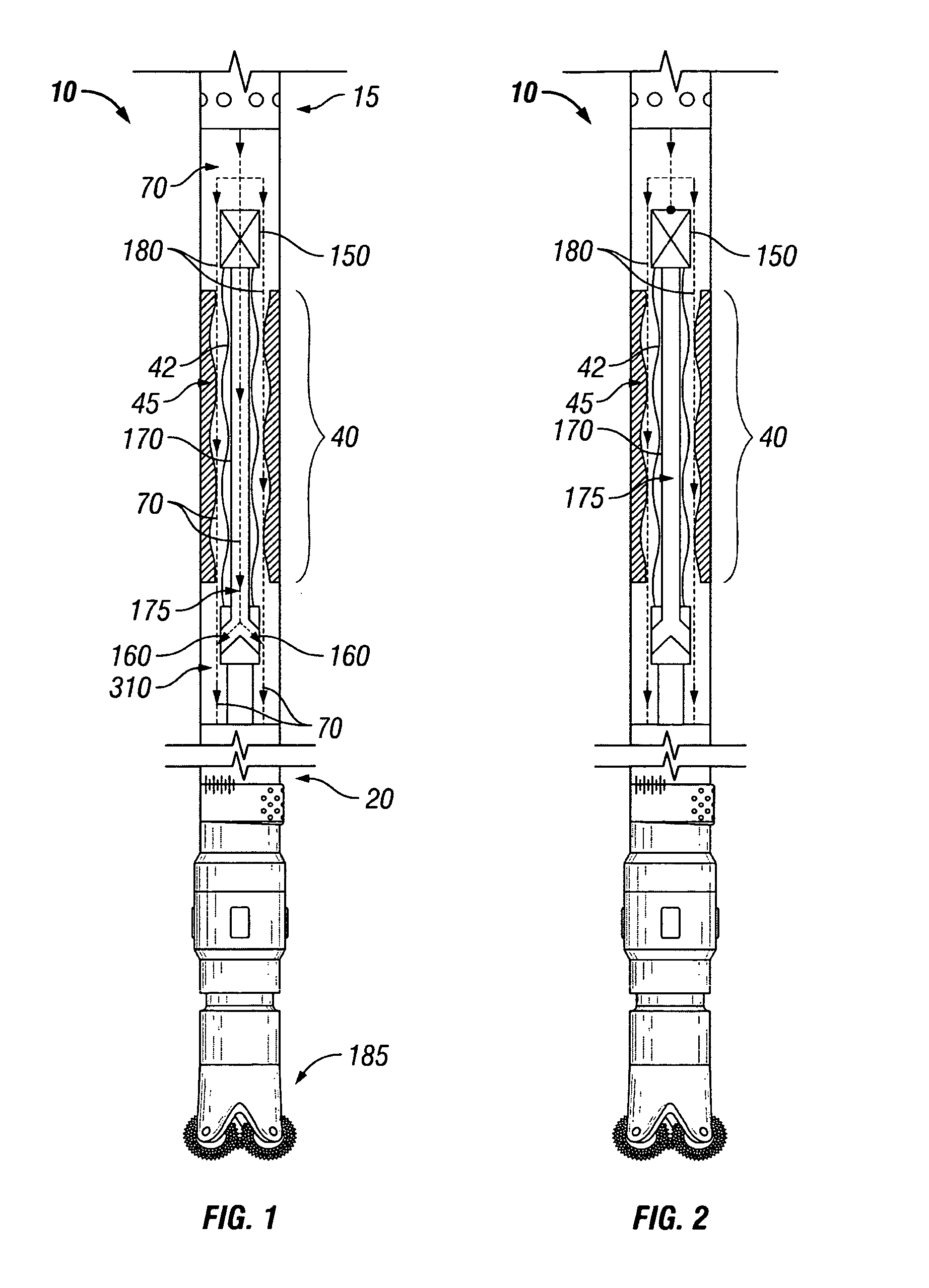
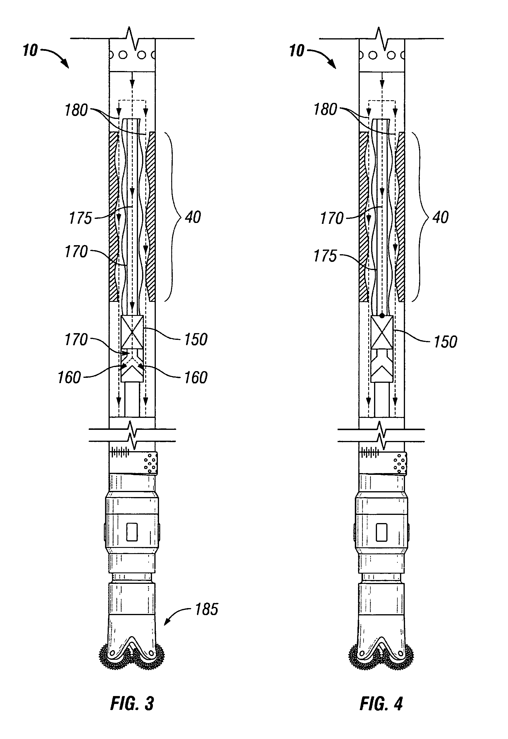
[0008]The present invention allows an operator to change the rotational speed of the drill bit by causing a portion of the fluid that is pumped through the drill string to bypass that part of the power section of a motor that imparts rotational motion on the drill bit without passing any of the fluid outside of the drill string. This is accomplished by means of a bypass valve installed inside, above, or below the power section of the motor.
[0009]The bypass valve separates the fluid flow through the power section into two paths. One path is directed through that part of the power section that causes the drill bit to rotate while the other path is directed around it. When the bypass valve acts to cause all of the fluid to flow through the power section of a motor, the drill bit will rotate at maximum speed. When the bypass valve acts to bypass a portion of the fluid through a port in the power section, the drill bit will rotate at a slower speed. The actual internal geometry of the fluid flow through the power section in conjunction with the fluid flow pressure maintained at the mud pump determines the actual speed of rotation. After the bypass valve separates the fluid into two flow paths, the flow is recombined inside the motor before it is channeled to the drill bit. This allows all of the fluid that flows down the drill string to cool the drill bit and to circulate the cuttings back up to the surface without any detrimental impact on system performance.
[0017]In even another embodiment, the amount of fluid that flows through the bypass valve when open is controllably selected by the size of a replaceable nozzle that installs inside the cam. The replaceable nozzle is configured to restrict a certain amount of flow through the cam and the housing when the bypass valve is open, thereby allowing a drilling operator to pre-set the speed of the drill bit.
[0018]In still another embodiment, the bypass valve may also be configured to open and close automatically based upon the type of formation encountered during drilling. When the drill bit encounters a harder formation, more weight is needed to press through it. The increased weight increases the friction on the bit and the pressure experienced by the motor. The bypass valve can be configured to respond to the increased pressure by, for example, opening one or more spring-loaded outlet valves. When the increased pressure experienced by the motor overcomes the closing forces of the spring-loaded outlet valves, the outlet valves open, diverting a portion of the fluid flow around the power section of the rotor and slowing the speed of the drill bit. The spring-loaded outlet valves may be configured to adjust to the amount of pressure experienced by the motor, allowing the amount of fluid to flow around the power section of the motor to be a function of the pressure experienced by the motor.

Problems solved by technology

In underbalanced drilling, the fluid pumped down the drill string is composed of a mixture of fluid and gas.

Method used


Image

  • Method and apparatus for shifting speeds in a fluid-actuated motor
  • Method and apparatus for shifting speeds in a fluid-actuated motor
  • Method and apparatus for shifting speeds in a fluid-actuated motor

Examples


Embodiment Construction

[0036]FIG. 1 is a diagram of an exemplary embodiment of a typical positive displacement motor 10 (“PDM”), or mud motor. The top side 15 of the motor connects to a drill string (not shown). The bottom side 20 connects to a drill bit 185. The power section 40 comprises a rotor 42 and stator 45. When a mud pump is turned on, fluid 70 enters the drill string, flows through the power section 40 and exits the bottom side 20 of the motor.

[0037]FIG. 2 is a diagram of an exemplary embodiment of a typical positive displacement motor 10 having a bypass valve 150 attached above the power section 40 of the motor 10; FIGS. 3 and 4 show the bypass valve 150 attached below the power section 40 of the motor 10; and FIGS. 5 and 6 show the bypass valve 150 attached inside the power section 40 of the motor. Because operation of the bypass valve is similar regardless of whether it attaches above, below, or inside the power section of a motor, only the operation of the bypass valve of FIGS. 1 and 2 need ...


PUM


Abstract

A method and apparatus for changing the speed of a drill bit down hole in a fluid-actuated motor, including a positive displacement motor and a hydraulic motor, is disclosed. The apparatus comprises a bypass valve installed in the motor for controlling flow through and around the power section of the motor. When closed, the bypass valve forces all fluid to flow through the power section of the motor, imparting maximum speed to the drill bit. When opened, a portion of the fluid flow is allowed to flow around the power section of the motor, thereby reducing the speed of the drill bit. The bypass valve may be opened or closed mechanically, electrically, hydraulically, pneumatically, or by any other means, including a removable plug.

Description

CROSS REFERENCE TO RELATED APPLICATION(S)[0001]This application claims priority from U.S. Provisional Patent Application No. 60 / 676,342, filed Apr. 30, 2005, by inventors Kosay El-Rayes, Nazeeh Melhem, and Peter Shwets, entitled “Method for Shifting Speeds in a Fluid-Actuated Motor,” which is hereby incorporated by reference.FIELD OF THE INVENTION[0002]The present invention generally relates to fluid-actuated motors, including positive displacement motors, known as Moineau pump-type drilling motors, and hydraulic motors, and specifically to a fluid-actuated motor having a variable rotor bypass valve installed therein to alter the rotational speed of the drill bit without the need for the motor to be removed from the well.BACKGROUND OF THE INVENTION[0003]In the oil drilling industry, there are two traditional methods of drilling an oil well. One is to attach a drill bit at the end of a drill string, apply downward pressure, and rotate the drill string from the surface so that the dri...

Claims


Application Information

Patent Timeline
Patent Type & Authority Patents(United States)
IPC IPC(8): E21B4/02
CPCE21B4/02F03C2/08F04C14/26Y10S415/903F04C14/08Y10T137/2663Y10T137/2693Y10T137/4658
Inventor EL-RAYES, KOSAY I.SHWETS, PETER J.MELHEM, NAZEEH
Owner NAT OILWELL DHT
Why Eureka
Try Eureka