Illumination optics and image projecting apparatus having thereof

an image projecting apparatus and optical technology, applied in the field of optical illumination and image projecting apparatus, can solve the problems of limited output, limited output as a system, limited heightening of brightness, etc., and achieve the effect of avoiding deterioration in image quality of projected imag

Active Publication Date: 2006-11-02
KONICA MINOLTA OPTO
View PDF4 Cites 23 Cited by
  • Summary
  • Abstract
  • Description
  • Claims
  • Application Information

AI Technical Summary

Benefits of technology

[0010] The present invention is devised in order to solve the above problems. It is an object of the present invention to provide an illumination optics in which a deterioration in a property of a color wheel is avoided so that the color wheel can be arranged on a light incident side of an integrator rod, so that color mixing is suppressed to minimum at the time of passing through the color wheel and a deterioration in image quality of a projected image can be avoided. Further, it is an object to provide an image projecting apparatus having such an illumination optics.

Problems solved by technology

Lamps, which are currently supplied and have short arc length, have good system efficiency, but their output is limited.
For this reason, in a system (image projecting apparatus) which use only one lamp, its output as a system is limited, and heightening of its brightness is limited.
Meanwhile, lamps having high output have a short life, and require frequent maintenance such as lamp exchange in the market.
As a result, color shading partially occurs on the modulation surface, the quality of the image to be projected onto a screen via the light modulating device is deteriorated.
When the boundary portions of the respective color filters cross the light emission surface of the integrator rod, switching of the light modulating device into an OFF state causes deterioration in light utilization efficiency (brightness), and thus the switching is not appropriate.
The respective color filters of the color wheel are formed by, for example, dielectric films, and thus their heat resistance is inferior.
For this reason, when the considerable heat energy is generated concentratedly one point of the color wheel or its vicinity, the property of the color wheel is deteriorated or changed.

Method used


Image

  • Illumination optics and image projecting apparatus having thereof
  • Illumination optics and image projecting apparatus having thereof
  • Illumination optics and image projecting apparatus having thereof

Examples


Embodiment Construction

[0021] One embodiment of the present invention is explained below with reference to the drawings.

(1. The Constitution of the Image Projecting Apparatus)

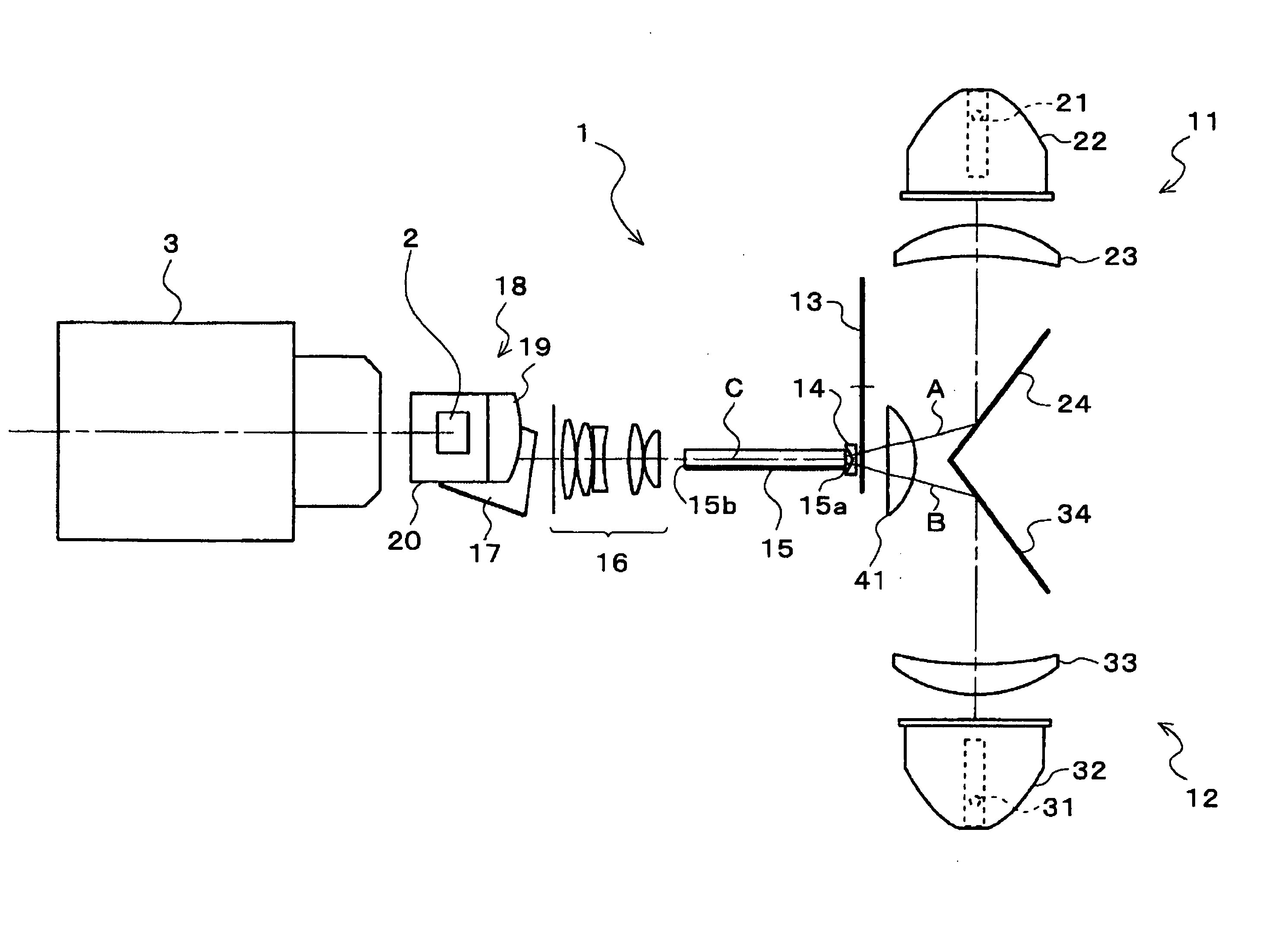
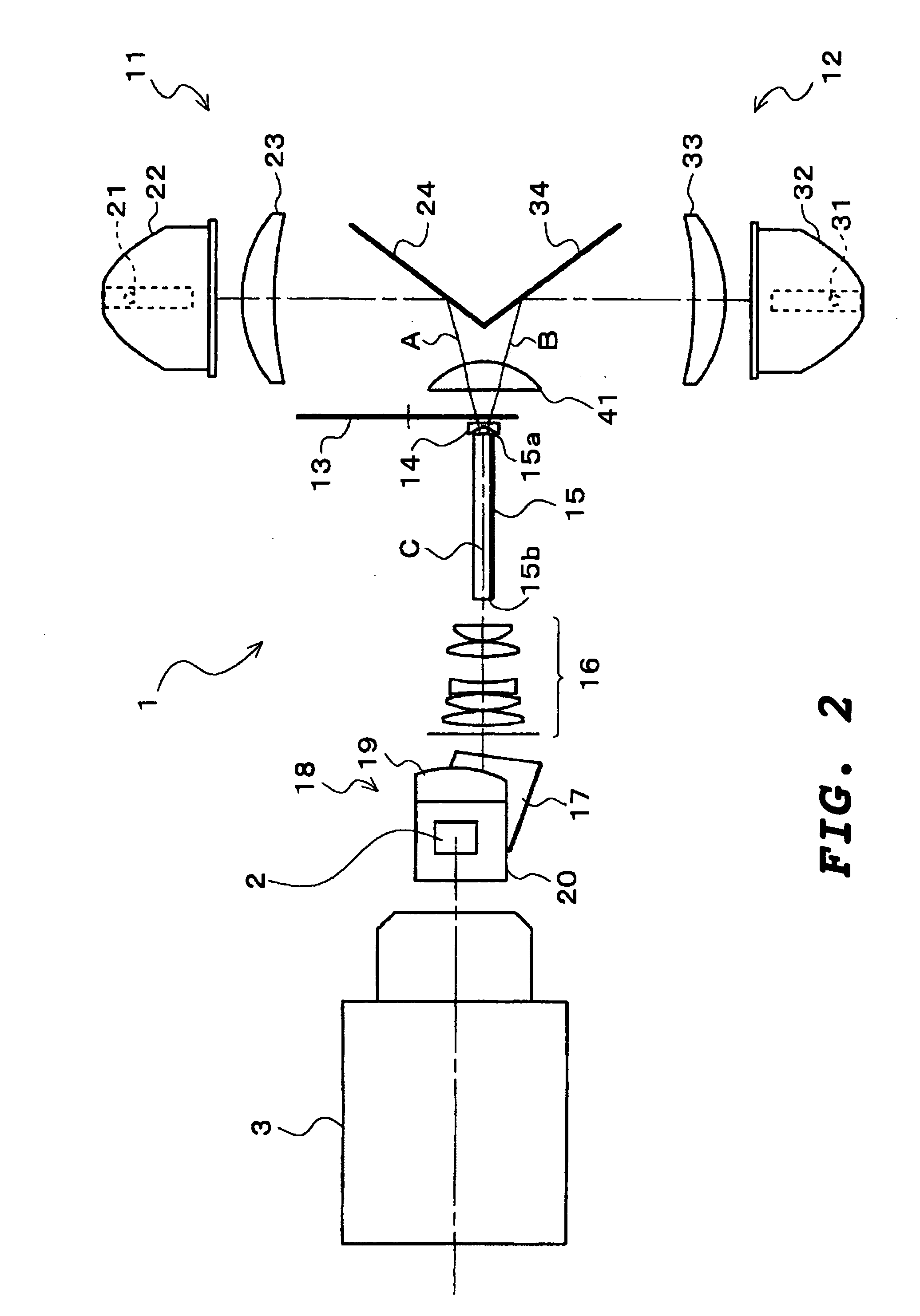
[0022]FIG. 2 is a plan view typically illustrating a schematic constitution of the image projecting apparatus according to an embodiment, and FIG. 3 is a side view of the image projecting apparatus. The image projecting apparatus of the embodiment has an illumination optics 1, a DMD 2 (Digital Micromirror Device; produced by Texas Instruments, Ltd.), and a projecting optics 3.

[0023] The illumination optics 1 is an optics for synthesizing emitted light beams from a plurality of light sources and supplying the synthesized light to the DMD 2, and its detailed constitution is mentioned later.

[0024] The DMD 2 is constituted so that micromirrors which tilt in an ON state or an OFF state according to image data of a display image are arranged in a matrix pattern, and it is a light modulating device which modulates the light supplied fr...


PUM


Abstract

An illumination optics includes a plurality of light source sections for emiting light beams and a time sharing color separation device having a plurality of color filters. The color filters are rotationally moved so as to cross optical paths of the emitted light beams from the light source sections, thereby separate the emitted light beams to enter there into different color light beams in a time-sharing state. The reference axes of the emitted light beams to enter the time sharing color separation device are separated from each other, and the color filters are formed so that border lines of the adjacent color filters cross the reference axes approximately simultaneously at the time of rotation.

Description

[0001] This application is based on the application No. 2005-129804 filed in Japan on Apr. 27, 2005, the entire content of which is hereby incorporated by reference. BACKGROUND OF THE INVENTION [0002] 1. Field of the Invention [0003] The present invention relates to an illumination optics and an image projecting apparatus having thereof. The invention relates to, for example, the illumination optics which is used for a projector and synthesizes light fluxes emitted from two lamps so as to supply the synthesized light flux to a light modulating device, and the image projecting apparatus having thereof. [0004] 2. Description of the Related Art [0005] Presently, high brightness is required in projectors, particularly, data projectors. Lamps, which are currently supplied and have short arc length, have good system efficiency, but their output is limited. For this reason, in a system (image projecting apparatus) which use only one lamp, its output as a system is limited, and heightening ...

Claims


Application Information

Patent Timeline
Patent Type & Authority Applications(United States)
IPC IPC(8): G03B21/14
CPCH04N5/74G03B21/208G03B21/2013
Inventor SAWAI, YASUMASAINOUE, KAZUHIKO
Owner KONICA MINOLTA OPTO
Why Eureka
Try Eureka