Image display apparatus and control method thereof

a technology of image display and control method, applied in the field of image display apparatus, can solve the problems of ineffective technologies, crosstalk (, poor image quality), etc., and achieve the effect of suppressing crosstalk and suppressing deterioration of image quality

Inactive Publication Date: 2012-02-23
CANON KK
View PDF5 Cites 22 Cited by
  • Summary
  • Abstract
  • Description
  • Claims
  • Application Information

AI Technical Summary

Benefits of technology

[0021]In the light of the above issues, it is an object of the present invention to provide a technology that allows effectively suppressing luminance fluctuation (crosstalk) caused by capacitive coupling between adjacent column wirings, in particular, suppressing deterioration of image quality derived from the in-plane distribution of luminance fluctuation.

Problems solved by technology

As a result, crosstalk (poor image quality) occurs on account of capacitive coupling (transverse electric field).
H6-258614 allow satisfactorily correcting the position-dependant fixed unevenness of display elements, such technologies are ineffective on display defects caused by so-called crosstalk in which the degree of unevenness varies depending on the display image.
Also, it has been found that some display defects remain uncorrected even when using technologies that involve correcting crosstalk on the basis of the display signal of an own pixel and display signals of adjacent pixels, as in Japanese Patent Application Laid-open No. 2006-23710.
Therefore, conventional correction methods are virtually ineffective when the distribution of crosstalk amount in the vertical direction (column direction) is large, as in the above-described problem, and / or when there is a left-right (row direction) distribution.

Method used


Image

  • Image display apparatus and control method thereof
  • Image display apparatus and control method thereof
  • Image display apparatus and control method thereof

Examples


first embodiment

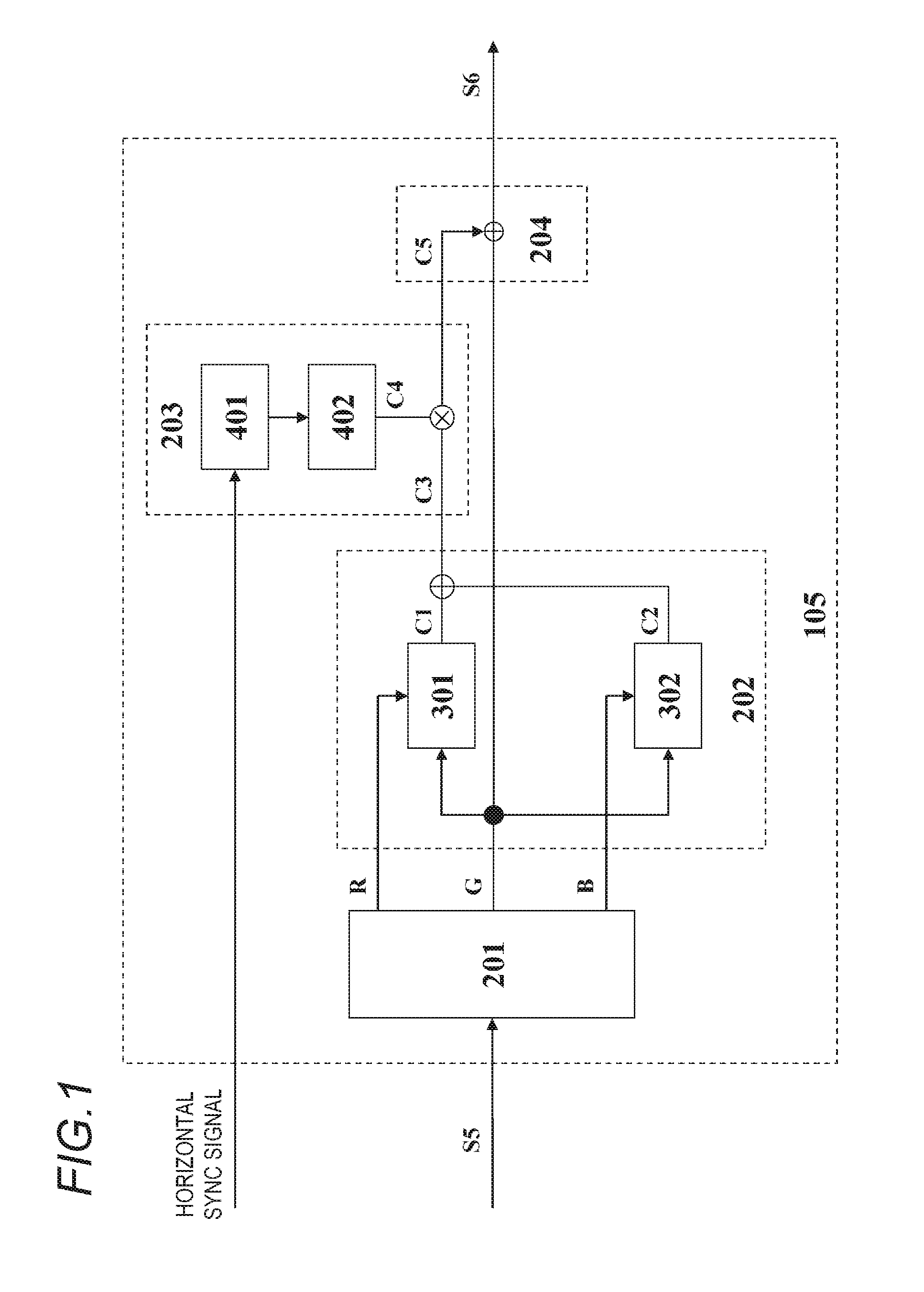
[0060]The crosstalk correction unit in a first embodiment of the present invention will be explained next based on FIG. 1. The crosstalk correction unit 105 can mainly comprise, for instance, a data sorting unit 201, a gradation combination correction unit 202, a column direction correction unit 203 and correction operation unit 204. In the present embodiment, the gradation combination correction unit 202 and the column direction correction unit 203 correspond to the correction value generation unit of the present invention, and the correction operation unit 204 corresponds to the correction operation unit of the present invention.

[0061]The corrected luminance data S5, having undergone fixed unevenness correction, is inputted to the data sorting unit 201. The data sorting unit 201 outputs, to the gradation combination correction unit, corrected luminance data S5 of a pixel to be crosstalk-corrected (own pixel) (G in FIG. 1) as well as corrected luminance data of pixels (adjacent pix...

second embodiment

[0076]A crosstalk correction unit in a second embodiment of the present invention will be explained next based on FIG. 8. The second embodiment is a configuration example of a crosstalk correction unit for solving display defects such as those of FIG. 12B that may occur at IC boundaries in the column drive circuit 12. The explanation below will refer only to features different from those of the first embodiment.

[0077]As illustrated in FIG. 8, the crosstalk correction unit 105 in the second embodiment has the data sorting unit 201, the first gradation combination correction unit 202, the first column direction correction unit 203 and the first correction operation unit 204. The configurations of the foregoing are identical to those of the first embodiment (FIG. 1). The crosstalk correction unit 105 of the present embodiment comprises a second gradation combination correction unit 206, a second column direction correction unit 207, a second correction operation unit 208 and a correcti...

third embodiment

[0083]A crosstalk correction unit in a third embodiment of the present invention will be explained based on FIG. 9, FIG. 10 and FIG. 11. The third embodiment is a configuration example of a crosstalk correction unit in a display device having a distribution (difference) of column wiring resistance and capacitance between adjacent column wirings, in the row direction, between the display region and the column drive circuit 12 (i.e. outside the display region).

[0084]In case of distribution of the column wiring resistance and the capacitance between column wirings, in the row direction, correction can be realized in accordance with the wiring resistance and capacitance between column wirings, for respective column wirings, by providing a plurality of types of correction circuits, as in the second embodiment. However, doing so is problematic in terms of the greater costs that are incurred on account of the larger memory and larger circuitry that accompany an increase in the number of co...


PUM


Abstract

An image display apparatus has a correction unit that performs a correction process on image signals so as to suppress luminance fluctuation caused by capacitive coupling between adjacent column wirings. The correction unit includes: a correction value generation unit that determines a correction value for a pixel to be corrected on the basis of a combination of a signal value of the pixel to be corrected and signal values of adjacent pixels which are on a column wiring next to a column wiring on which the pixel to be corrected is, and on the basis of a position of the pixel to be corrected in a column direction; and a correction operation unit that corrects a signal of the pixel to be corrected using the correction value generated by the correction value generation unit.

Description

BACKGROUND OF THE INVENTION[0001]1. Field of the Invention[0002]The present invention relates to an image display apparatus in which crosstalk generated in a matrix-driven display panel is suppressed, and to a control method of the image display apparatus.[0003]2. Description of the Related Art[0004]Known flat panel displays (FPDs) include liquid crystal display devices (LCDs), plasma display devices (PDPs), organic EL display devices (OLEDs) and field emission display devices (FEDs).[0005]Among the foregoing, FEDs have a passive matrix structure, i.e. a simple panel structure in which field emission elements are positioned at intersections of row wirings and column wirings. As a result, FEDs have characteristically a fast response at a low cost.[0006]FIG. 2 is a basic configuration example of an ordinary matrix-driven image display apparatus (for instance, an FED). A plurality of column wirings 14 and a plurality of row wirings 15 are formed on a rear plate 16. Pixels (display elem...

Claims


Application Information

Patent Timeline
Patent Type & Authority Applications(United States)
IPC IPC(8): G09G5/10
CPCG09G2320/0209G09G3/20
Inventor KOBAYASHI, KOJI
Owner CANON KK
Why Eureka
Try Eureka