Optical writing device, image forming apparatus, and method and program product for controlling optical writing device

a technology of optical writing and image forming, which is applied in the direction of electrographic process, recording apparatus, instruments, etc., can solve the problems of increasing the cost of the entire device, skewing the writing type, and skewing the scanning beam

Inactive Publication Date: 2012-03-15
RICOH KK
View PDF3 Cites 22 Cited by
  • Summary
  • Abstract
  • Description
  • Claims
  • Application Information

AI Technical Summary

Benefits of technology

[0017]It is an object of the present invention to at least partially solve the problems in the conventional technology.

Problems solved by technology

In such an optical writing device, the LD raster optical system type has an error due to skew, positional shift, etc. of an f-theta lens and a reflecting mirror; the LED writing type has skew, an installation error, etc. of the LEDA head.
One of problems caused by such an error is skew of a scanning beam, i.e., a problem that a main scanning direction of an optical beam is inclined from an original direction.
In the method to mechanically correct the skew, correction is achieved by providing an adjustment mechanism which displaces the mounting positions of a mirror and a head in a writing unit in the case of the LD type and the mounting position of the LEDA in the case of the LED type; however, to automatically carry out this adjustment, an actuator, such as a motor, is required, and this results in an increase in cost of the entire device.
However, in the method to correct skew by image processing, a change in dither pattern arises at the image shift position.
In a case of using the technology disclosed in Japanese Patent Application Laid-open No. 2009-27683, image shift is performed while avoiding an area of dither matrix; therefore, the image shift period has to be at least longer than the area of dither matrix, and the number of correctable lines is limited.
Furthermore, this technology cannot be applied to such an image that a dither pattern is expanded over the whole page.
H11-70697, a configuration of a circuit for controlling the timing to emit a light with respect to each element is complex, resulting in increases in the circuit size and cost.
In this case, there is individual variability in skew among optical writing devices, so the optical writing device has to input skew information to the controller, and this constrains the design of the optical writing device and the controller.
Moreover, it is uncertain what kind of skew information is input from the optical writing device; therefore, at the time of design of a skew correction function of the controller, it is necessary to design the skew correction function so as to deal with any kind of skew or design the skew correction function to meet skew which has occurred in the optical writing device, and this results in constraints on the design and an increase in cost.

Method used


Image

  • Optical writing device, image forming apparatus, and method and program product for controlling optical writing device
  • Optical writing device, image forming apparatus, and method and program product for controlling optical writing device
  • Optical writing device, image forming apparatus, and method and program product for controlling optical writing device

Examples


Embodiment Construction

[0040]Exemplary embodiments of the present invention are explained in detail below with reference to the accompanying drawings. In the present embodiments, a multifunction peripheral (MFP) is described as an example of an image forming apparatus. The image forming apparatus according to the present embodiments is an electrophotographic MFP, and the gist of the invention is the mode of skew correction made in an optical writing device for forming an electrostatic latent image on a photoreceptor. Incidentally, the image forming apparatus does not have to be an MFP; for example, the image forming apparatus can be a copier, a printer, a facsimile machine, and the like.

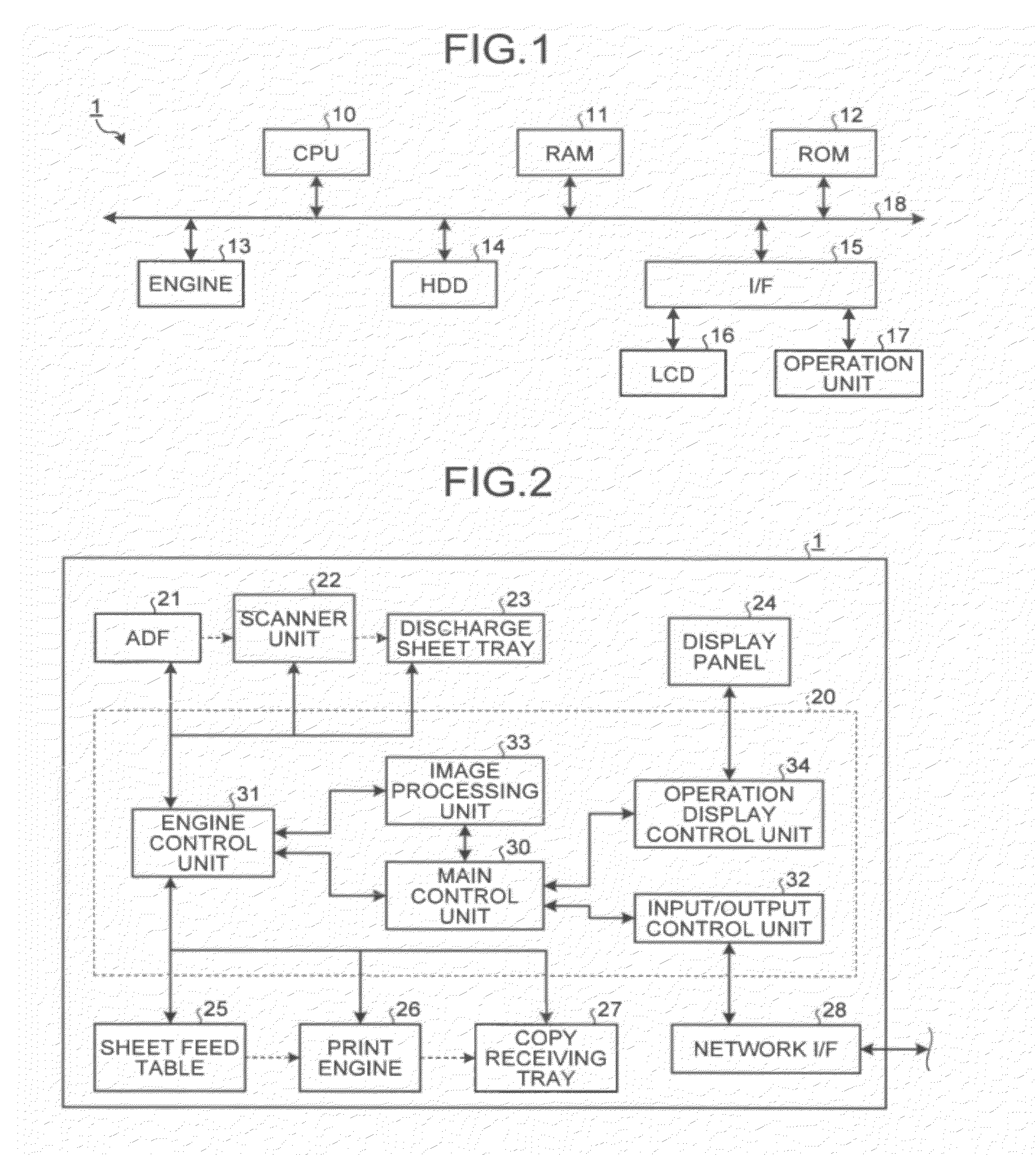
[0041]FIG. 1 is a block diagram showing a hardware configuration of an image forming apparatus 1 according to an embodiment of the present invention. As shown in FIG. 1, the image forming apparatus 1 according to the present embodiment has an engine for performing image formation in addition to the same configuration as a ...


PUM


Abstract

An optical writing device that forms an electrostatic latent image on a photoreceptor. The device includes a pixel-information acquiring unit, a line-pixel-information storage unit that stores the acquired pixel information corresponding to a plurality of lines for each main scanning line, a light source device that exposes the photoreceptor with a period corresponding to an N-fold sub-scanning direction resolution of the pixel information, a positional-shift-information storage unit that stores a positional shift information, a sub-line counting unit that counts a sub-line period, a reading-line selecting unit that performs N times of selection that determines which main scanning line is selected as the line from which the pixel information is read out, on the basis of a calculated value from the counted value of the sub-line period and the positional shift information, and a pixel-information reading unit.

Description

CROSS-REFERENCE TO RELATED APPLICATIONS[0001]The present application claims priority to and incorporates by reference the entire contents of Japanese Patent Application No. 2010-206782 filed in Japan on Sep. 15, 2010.BACKGROUND OF THE INVENTION[0002]1. Field of the Invention[0003]The present invention relates to an optical writing device, an image forming apparatus, a method and program for controlling the optical writing device, and a recording medium, and more particularly, to skew correction of an image while suppressing degradation of the image quality.[0004]2. Description of the Related Art[0005]Recently, digitization of information tends to be promoted, and image forming apparatuses, like printers and facsimile machines used for output of digitized information and scanners used for digitization of documents, have become essential apparatuses. Many image forming apparatuses include imaging functions, image forming functions, communication functions, and the like, to be configur...

Claims


Application Information

Patent Timeline
Patent Type & Authority Applications(United States)
IPC IPC(8): B41J2/385
CPCG03G15/043H04N1/3878
Inventor MIYADERA, TATSUYAKOMAI, KUNIHIROKINOSHITA, IZUMISHIRASAKI, YOSHINORISHIKAMA, TAKESHIYOKOYAMA, TAKUHEIYAMAGUCHI, AKINORI
Owner RICOH KK
Why Eureka
Try Eureka