Image reading device and image forming apparatus

a reading device and reading technology, applied in the direction of digital output to print units, instruments, electrographic processes, etc., can solve the problems of reducing the productivity of reading using the twain, affecting the life of the illumination lamp, and the white patch of the original is likely to become whi

Active Publication Date: 2009-05-21
RICOH KK
View PDF17 Cites 68 Cited by
  • Summary
  • Abstract
  • Description
  • Claims
  • Application Information

AI Technical Summary

Benefits of technology

[0019]It is an object of the present invention to at least partially solve the problems in the conventional technology.

Problems solved by technology

Due to this, a white patch of the original is likely to become data that is black textured and that includes significant noise.
Due to this, the productivity when reading using the TWAIN is further reduced.
However, due to the control mentioned earlier, because the illumination lamp is always switched on during the predetermined time, a life of the illumination lamp is reduced.

Method used


Image

  • Image reading device and image forming apparatus
  • Image reading device and image forming apparatus
  • Image reading device and image forming apparatus

Examples


first embodiment

[0034]FIG. 8 is a schematic diagram of a structure of an image reading device 1 according to the present invention. As shown in FIG. 8, the image reading device 1 includes a reading unit 100 and an automatic document feeder (ADF) 200. The ADF 200 drives a pickup roller 201, a conveying roller 202, and a conveying drum 203. Due to this, a sheet shaped original D, which is placed on an original tray 204, is conveyed at a constant speed such that the original D passes a position of an original reading glass 101. The conveyed original D is ejected into a discharge tray 205. Alternately, the original D is switched back by a switchback unit 207 that is in the upper direction of the discharge tray 205 by operating a branching pawl 206. Due to this, the original D is reversed and again conveyed onto the original reading glass 101. After the image reading device has read the other surface of the original D, the original D is ejected into the discharge tray 205.

[0035]A contact glass 102, a st...

second embodiment

[0047]In the present invention, after reading completion of the original D in the DF mode, upon satisfaction of predetermined conditions, for example, if the original D is set in a platen of the ADF 200 and the ADF 200 is closed, the first and the second carriages 111 and 112 read the standard white plate 103 and await at the DF mode reading position HP while the lamp 104 is still switched on. If the next read request is issued within the predetermined time, the first and the second carriages 111 and 112 read the original D and carry out correction using a standard white plate data that is retrieved before.

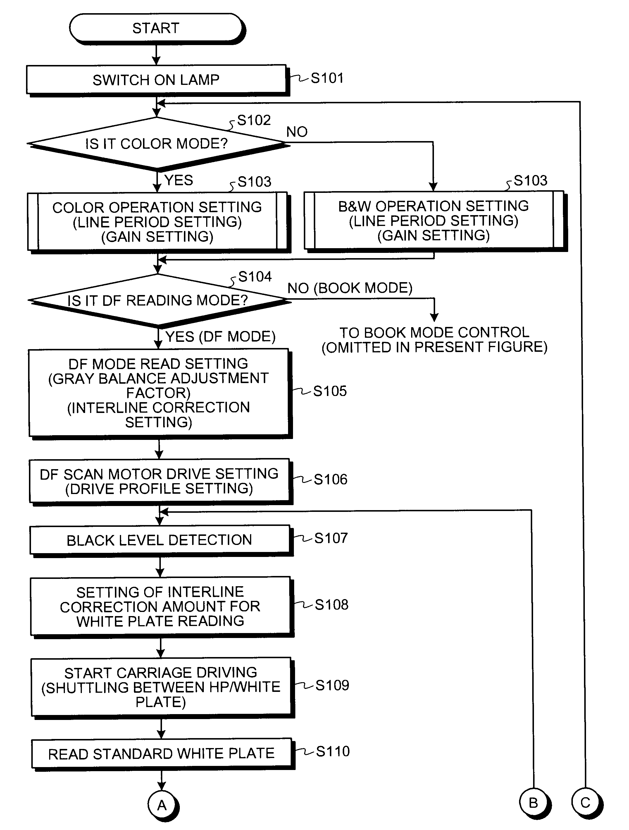
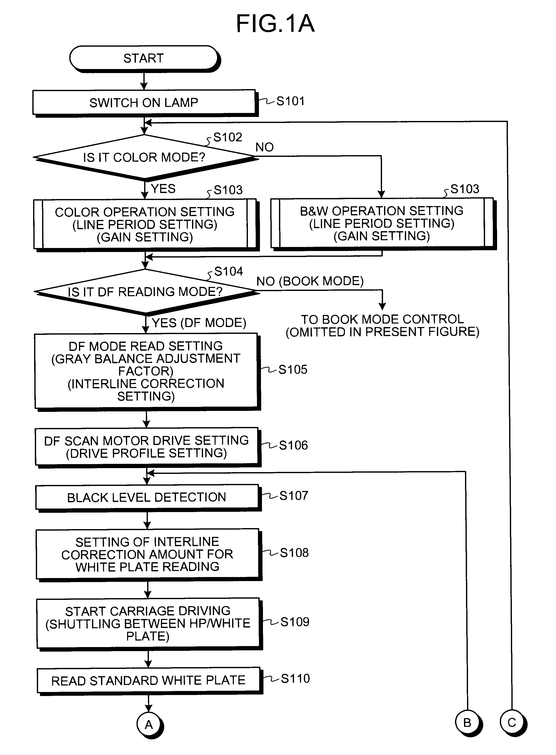
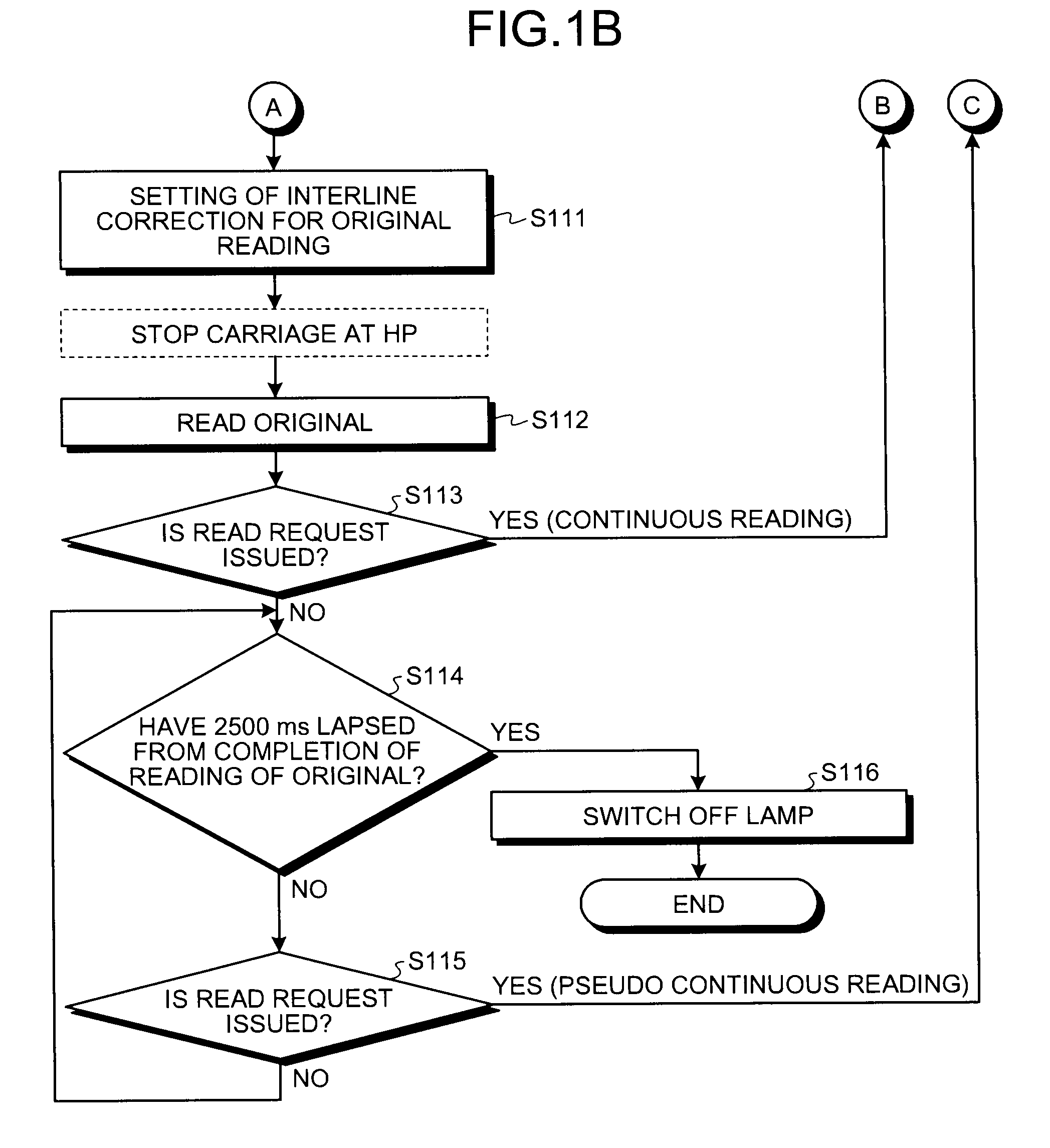
[0048]FIGS. 3A and 3B are flowcharts of a process according to the second embodiment. In the second embodiment, a determining process at Step S301 is carried out between Steps S107 and S108 in the process according to the first embodiment that is shown in FIGS. 2A and 2B. Further, a process at Steps S302 to S305 is carried out between Steps S114 and S115 in the process according t...

third embodiment

[0054]In the present invention, if a currently requested reading mode differs from a previous reading mode (a color mode or a B&W mode), the first and the second carriages 111 and 112 newly read the standard white plate data and subsequently read the original D.

[0055]FIGS. 4A and 4B are flowcharts of a process according to the third embodiment. In the third embodiment, a determination at Step S401 is further added with respect to a determination result at Step S301 in the second embodiment that is shown in FIGS. 3A and 3B. The rest of the steps are the same as the respective steps of the process shown in FIGS. 3A and 3B. In other words, the control unit 120 confirms whether the standard white plate data has been read while waiting at Step S301 shown in FIG. 4A. If the standard white plate data has not been read, the control unit 120 unconditionally reads the standard white plate data after Step S108. If the standard white plate data has been read, the control unit 120 determines whe...


PUM


Abstract

In a first mode, an original is read with a first and a second carriages stopped. In a second mode, the original is read with the first and the second carriages moving in a sub-scanning direction with a distance between the original and an optical reading element kept constant. A control unit causes, if a predetermined condition is satisfied after reading the original in the first mode, the first and the second carriages to standby at a reading position of the first mode while keeping the light source turned on, and if a next read request is issued within a predetermined time, causes the first and the second carriages to move to a next reading operation.

Description

CROSS-REFERENCE TO RELATED APPLICATIONS[0001]The present application claims priority to and incorporates by reference the entire contents of Japanese priority document 2007-299625 filed in Japan on Nov. 19, 2007.BACKGROUND OF THE INVENTION[0002]1. Field of the Invention[0003]The present invention relates to an image reading device for a digital copier, a scanner, a facsimile, and the like and an image forming apparatus that employs the image reading device.[0004]2. Description of the Related Art[0005]The TWAIN is known as one of technical standards for connecting an image input device such as a scanner, a digital camera, and the like to a personal computer, which means that, if a device is compatible with the TWAIN, an image can be input from all application softwares that are compatible with the TWAIN.[0006]Technologies related to an image reading device are disclosed in, for example, Japanese Patent Publication No. 3553363 and Japanese Patent Application Laid-open No. H11-136454. ...

Claims


Application Information

Patent Timeline
Patent Type & Authority Applications(United States)
IPC IPC(8): H04N1/40
CPCH04N1/4076H04N1/04
Inventor INAGE, OSAMU
Owner RICOH KK
Why Eureka
Try Eureka