Optical scanning device and image forming apparatus

a scanning device and image forming technology, applied in the direction of optics, electrographic process devices, instruments, etc., can solve the problems of noise generation, wear-out of bearings, and generation of hea

Inactive Publication Date: 2006-11-02
RICOH KK
View PDF1 Cites 79 Cited by
  • Summary
  • Abstract
  • Description
  • Claims
  • Application Information

AI Technical Summary

Benefits of technology

[0022] It is an object of the present invention to at least solve the problems in the conventional technology.

Problems solved by technology

This raises issues such as wear-out of bearings, generation of heat due to windage loss, and generation of noise, which puts a limit on high-speed scanning.
The resonance frequencies, however, may not always coincide because of the moment of inertia of the vibrating units and the spring constant of the twisting members, which tend to vary due to the fluctuations in dimensions caused during the producing process.
Because each vibration mirror is individually driven, if the resonance frequencies do not coincide with one another, scan line pitches become uneven, resulting in displacement of the scanning lines that occurs gradually from the starting point to the end point in the sub-scanning direction.
This causes displacements of registers and unevenness in density among images of different colors, resulting in color shifts and discoloration.
Thus, the image quality is degraded.
Another limit is that the variation amount of the rotation angle per unit time drastically decreases in accordance with sinusoidal vibration as the scan angle nears its peak.
For this reason, the situation is becoming more difficult to ensure a sufficient scan angle.
It is still difficult, however, to make the resonance frequencies exactly match.
In the current situation in which of an image formation spot having a smaller diameter is demanded as a higher image quality is required, the mirror surface size cannot help but be increased.
Therefore, the measures that use an increased torque for compensation are becoming less effective.
Nevertheless, individual control of the starting positions between the opposing stations, which is enabled only with multiple vibration mirrors, will no longer be possible with a single mirror.

Method used


Image

  • Optical scanning device and image forming apparatus
  • Optical scanning device and image forming apparatus
  • Optical scanning device and image forming apparatus

Examples


first embodiment

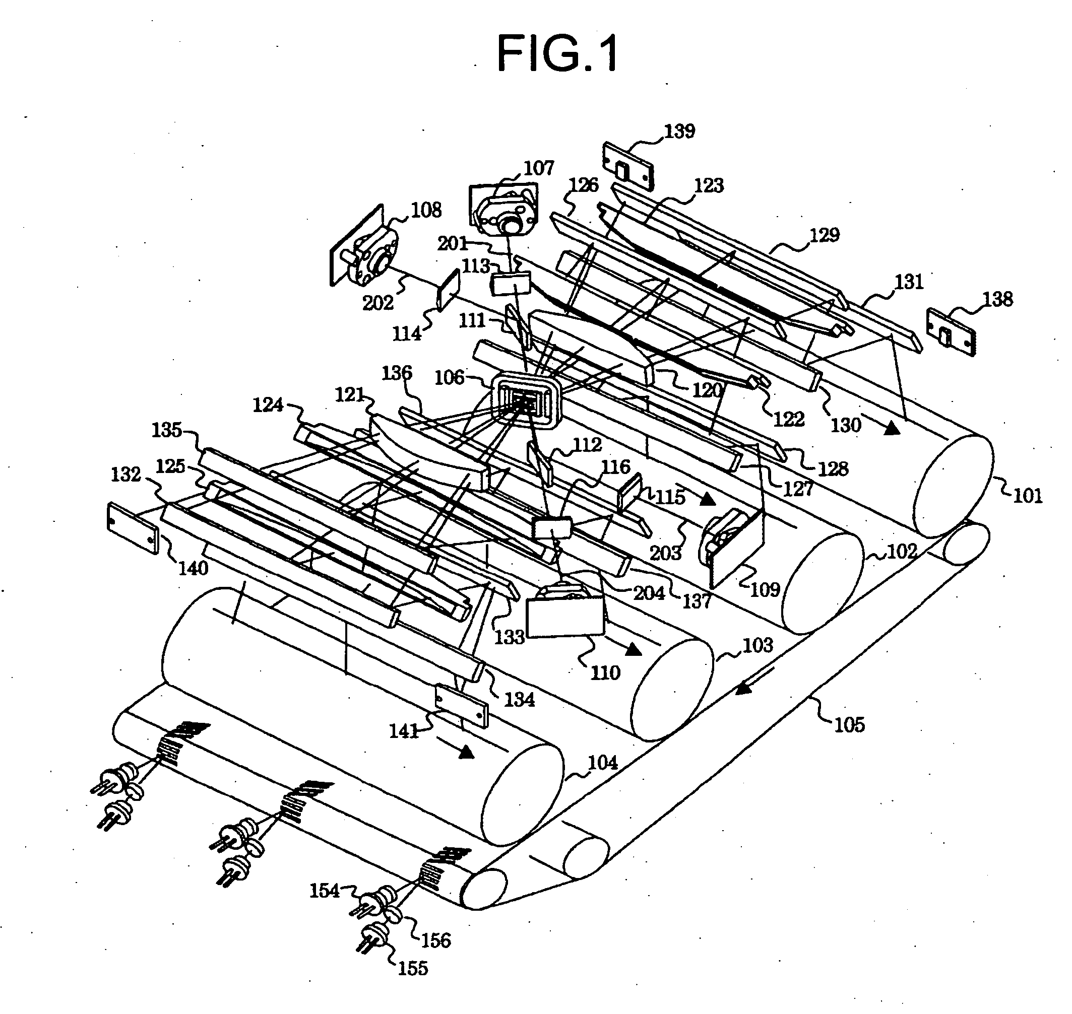
[0046]FIG. 1 is a perspective for explaining a first embodiment according to the present invention.

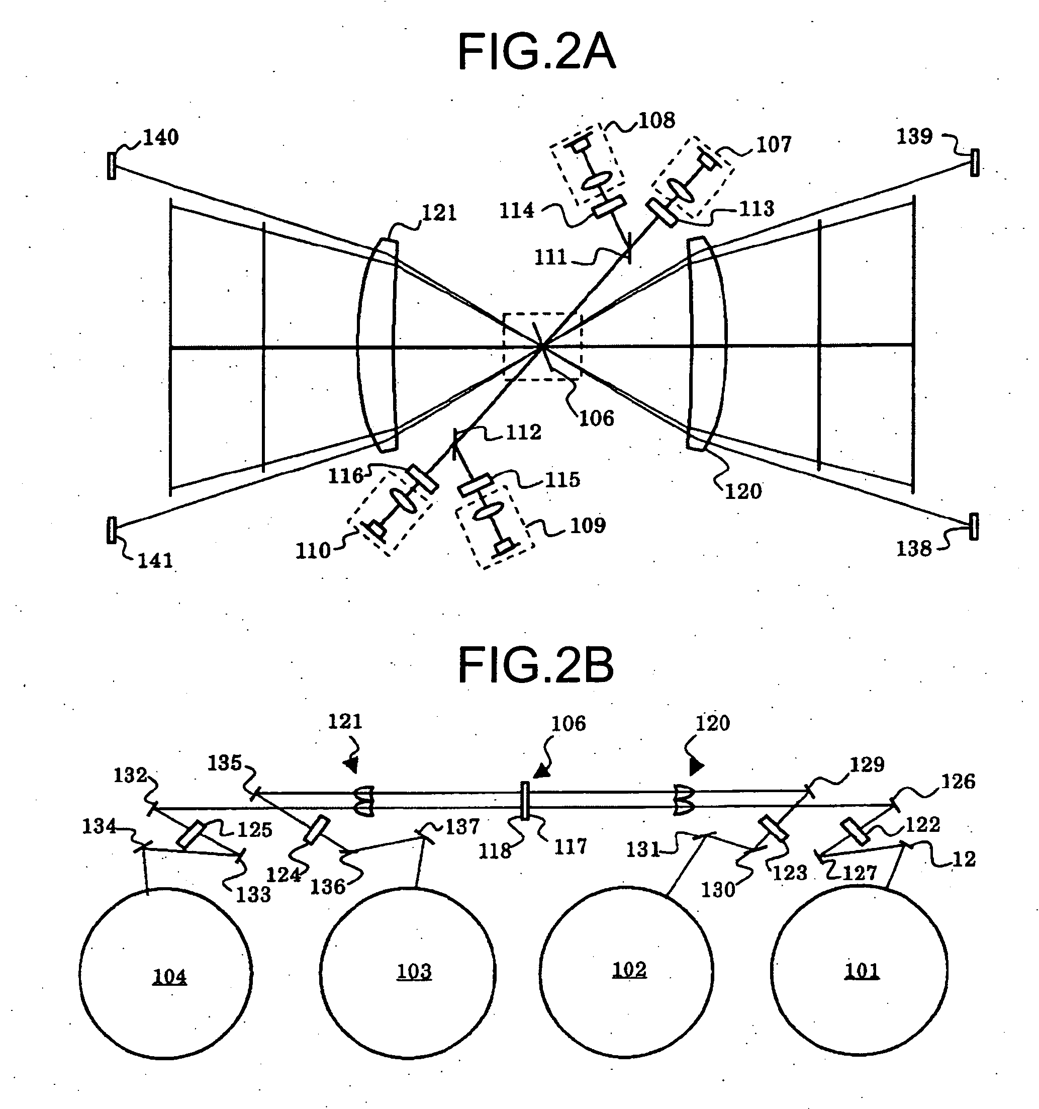
[0047] Reference numerals 101 through 104 in the drawing designate photosensitive drums that are to be scanned, 105 designates a transfer belt, 106 designates a vibration mirror module (hereinafter, “vibration mirror”), 107 through 110 designate light source units, 111 and 112 designate incident mirrors, and 113 through 116 designate cylinder lenses. Other reference numerals will be referred to in the explanation where they appear.

[0048] The optical scanning device shown in FIG. 1 corresponds to a tandem image forming apparatus having four stations. The stations are divided into two two-station groups. Beams are projected on a single-body vibration mirror in which the reflective surfaces are arranged back-to-back in opposite directions, and deflected for scanning. The single-body vibration mirror may have a structure in which reflective surfaces are provided on both sides of a single ...


PUM


Abstract

A vibration mirror used in an optical scanning device has two reflection surfaces on opposite sides. A pair of light beams corresponding to a pair of different colors are irradiated on one reflection surface and another pair of light beams corresponding to another pair of different colors are irradiated on other reflection surface. If there are fluctuations in dimensions or a change in temperature, because the vibration mirror is one, all the colors are subjected to the same influences.

Description

CROSS-REFERENCE TO RELATED APPLICATIONS [0001] The present document incorporates by reference the entire contents of Japanese priority document, 2005-111297 filed in Japan on Apr. 7, 2005. BACKGROUND OF THE INVENTION [0002] 1. Field of the Invention [0003] The present invention relates to an optical scanning device and an image forming apparatus such as a digital copier and a laser printer that includes the optical scanning device. [0004] 2. Description of the Related Art [0005] Examples of deflectors used in conventional optical scanning devices for scanning a target surface with light include a polygon mirror and a galvanometer mirror. To achieve higher-resolution images and higher-speed printing, the mirror needs to be rotated at higher speed. This raises issues such as wear-out of bearings, generation of heat due to windage loss, and generation of noise, which puts a limit on high-speed scanning. [0006] Recently, to address such issues, studies have been conducted on deflectors ...

Claims


Application Information

Patent Timeline
Patent Type & Authority Applications(United States)
IPC IPC(8): H04N1/04
CPCG03G2215/0404H04N1/1135G03G15/0435H04N2201/0446H04N1/12
Inventor AKIYAMA, HIROSHIHAYASHI, YOSHINORINAKAJIMA, TOMOHIRO
Owner RICOH KK
Why Eureka
Try Eureka