Display device and display driving method

a display device and driving method technology, applied in the direction of static indicating devices, instruments, etc., can solve the problems of high power consumption of such devices, difficult to achieve both power consumption reduction and general image quality enhancement for bright and beautiful display, etc., to reduce the potential difference from the signal value voltage, suppress image quality lowering, and reduce the effect of the entire luminan

Inactive Publication Date: 2009-03-26
SONY CORP
View PDF6 Cites 24 Cited by
  • Summary
  • Abstract
  • Description
  • Claims
  • Application Information

AI Technical Summary

Benefits of technology

[0009]Japanese Patent Laid-open No. 2005-301234 discloses a display device that is a self-luminous display based on a passive-matrix drive system. In this display device, control of the threshold voltage and processing of expanding a video signal are carried out depending on the overall signal level of the display contents so that displaying with higher luminance may be allowed for video with a high overall signal level and darkening of black may be allowed for video with a low overall signal level. This allows the display device to have improved contrast and enhanced luminance according to this patent document.
[0020]This feature offers an advantageous effect that suppression of the entire luminance, i.e., suppression of the power consumption, can be realized while image quality lowering is suppressed to the minimum through simple control: the change of the signal amplitude reference voltage.

Problems solved by technology

Although some organic EL displays have been put into practical use, high power consumption thereof is still being regarded as a problem.
For the organic EL display, suppression of the power consumption and suppression of the influence of sudden load changes are considered to be large challenges that should be dealt with, from the viewpoint of allowing decrease in the power consumption of the entire device and reduction of the scale of the power supply system, and this is common to all the display devices.
Thus, it is considered that it is difficult to achieve both general image quality enhancement for realization of bright and beautiful displaying and power consumption reduction.

Method used


Image

  • Display device and display driving method
  • Display device and display driving method
  • Display device and display driving method

Examples


Embodiment Construction

[0030]A display device and a display driving method according to embodiments of the present invention will be described below.

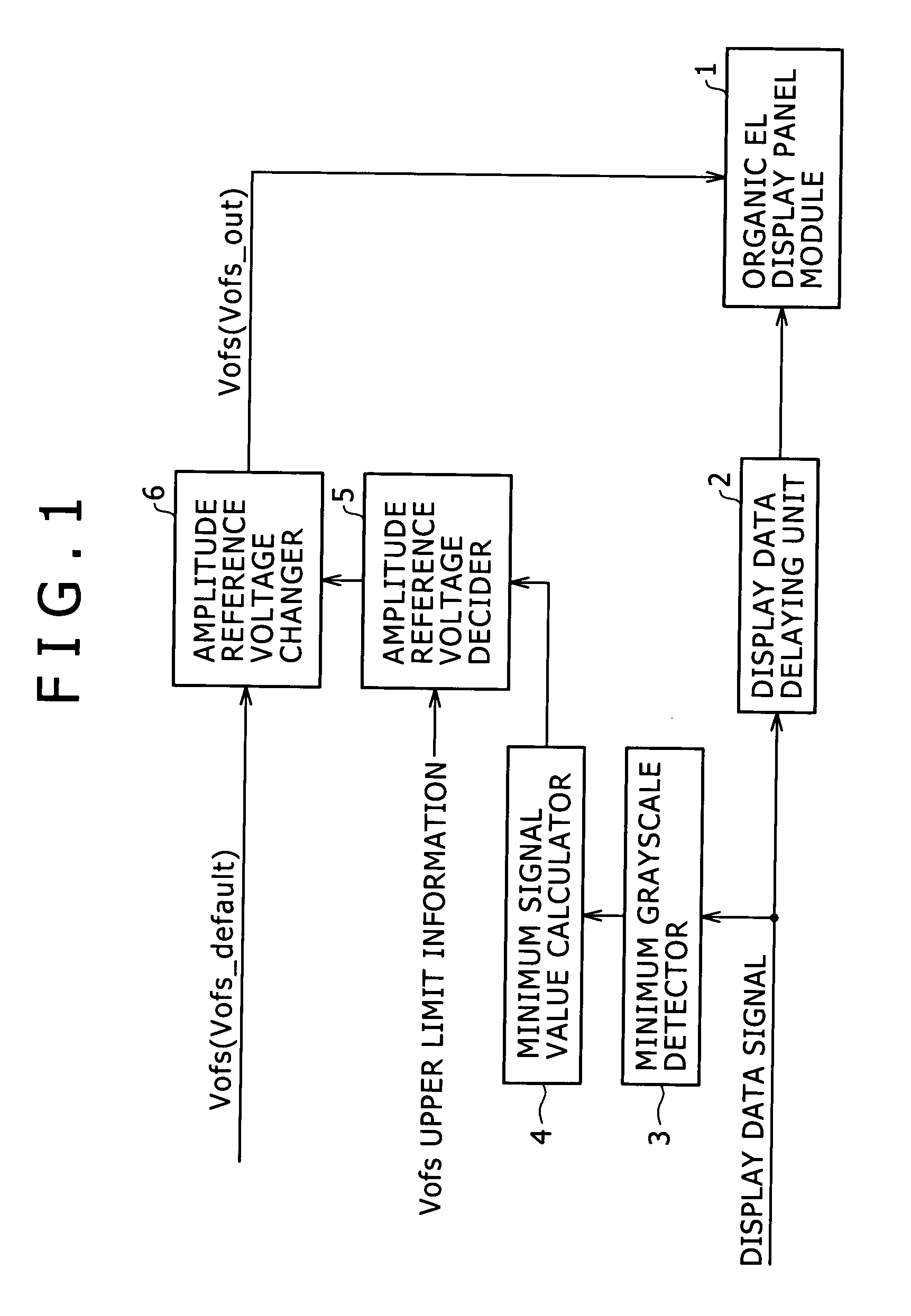
[0031]FIG. 1 shows the configuration of the display device of the embodiment. The display device of the present example includes an organic EL display panel module 1 in which organic EL devices are used as light emitting devices, a display data delaying unit 2, a minimum grayscale detector 3, a minimum signal value calculator 4, an amplitude reference voltage decider 5, and an amplitude reference voltage changer 6.

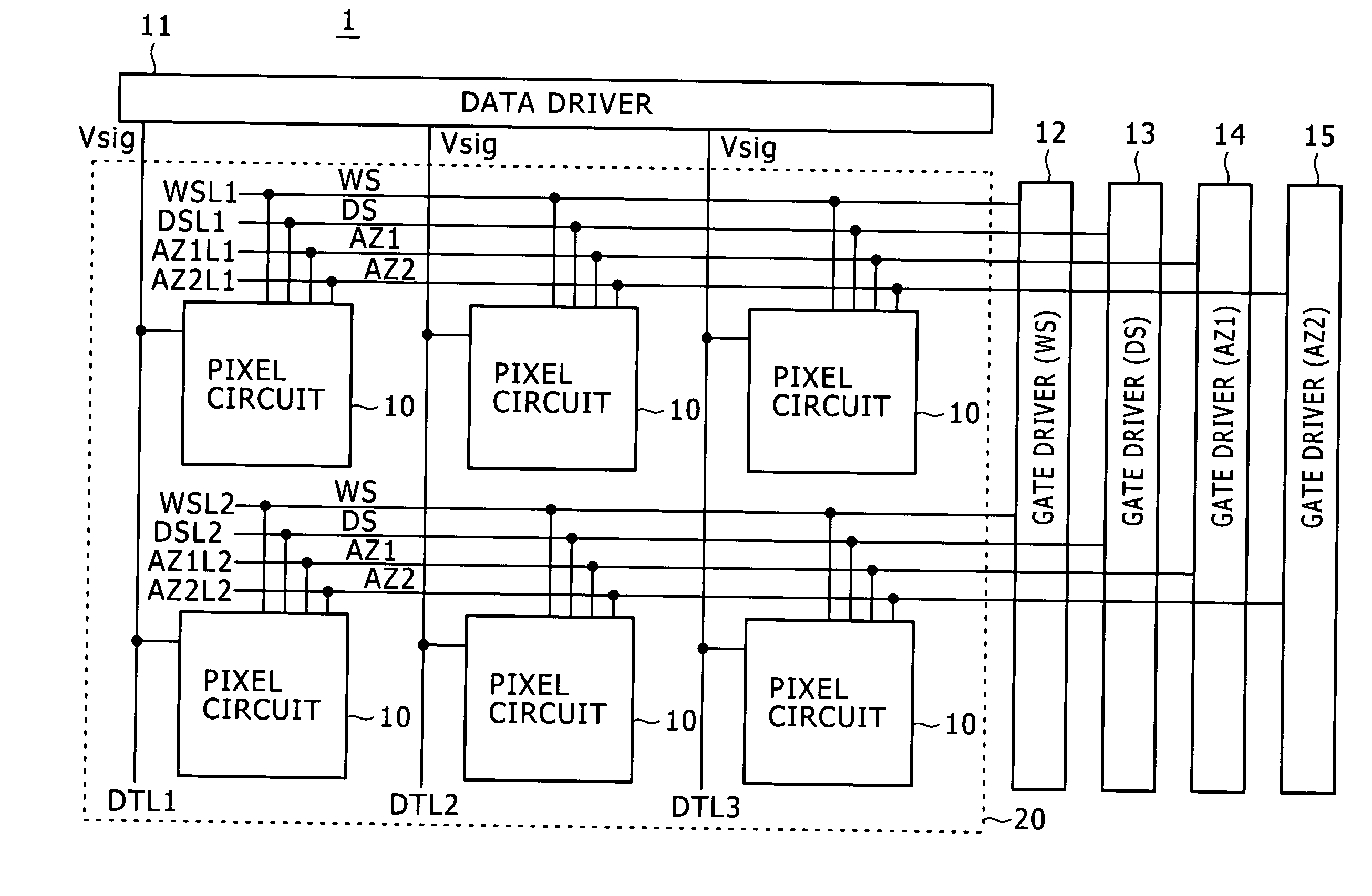
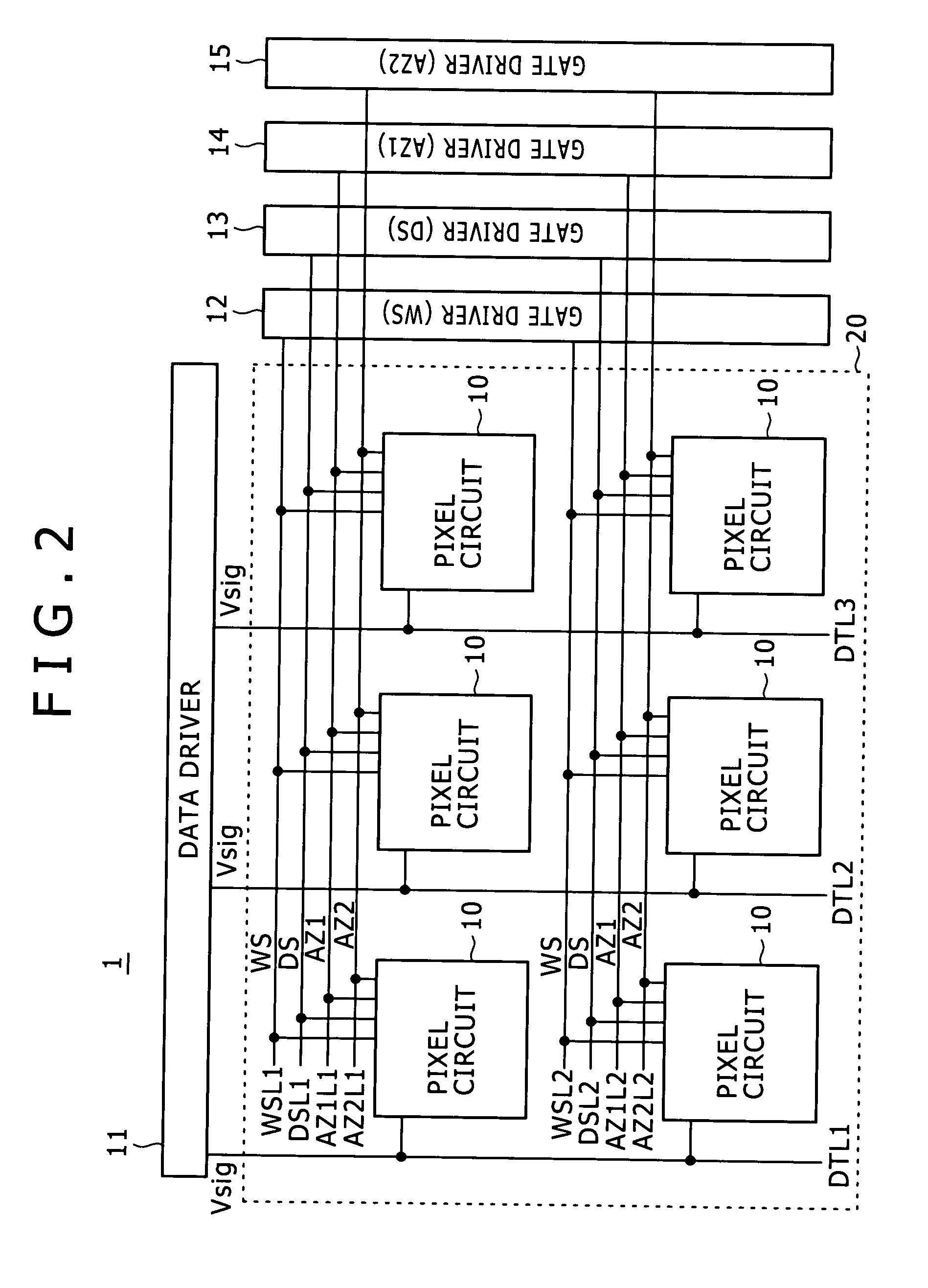
[0032]Initially the organic EL display panel module 1 will be described below with reference to FIGS. 2, 3, and 4.

[0033]FIG. 2 shows one example of the configuration of the organic EL display panel module 1. This organic EL display panel module 1 includes pixel circuits 10 which each include an organic EL device as a light emitting device and carry out light emission driving based on an active-matrix system.

[0034]As shown in FIG. 2, the organic EL d...


PUM


Abstract

A display device includes a display panel unit configured to include pixel circuits in each of which an organic electroluminescence device is used as a light emitting device and is driven to emit light with luminance dependent upon a voltage difference between a signal value voltage of an input display data signal and a signal amplitude reference voltage. The display device further includes: a voltage controller configured to carry out grayscale value detection for a display data signal to be supplied to the display panel unit in every predetermined period, and create voltage control information of the signal amplitude reference voltage by using a detected grayscale value; and a signal amplitude reference voltage changer configured to change a voltage value of the signal amplitude reference voltage to be supplied to the pixel circuits of the display panel unit, based on voltage control information created by the voltage controller.

Description

CROSS REFERENCES TO RELATED APPLICATIONS[0001]The present invention contains subject matter related to Japanese Patent Application JP 2007-243607 filed in the Japan Patent Office on Sep. 20, 2007, the entire contents of which being incorporated herein by reference.BACKGROUND OF THE INVENTION[0002]1. Field of the Invention[0003]The present invention relates to a display device employing organic electroluminescence devices (organic EL devices) as light emitting devices and a display driving method therefor.[0004]2. Description of the Related Art[0005]Flat panel displays are widely used for products such as computer displays, portable terminals, and television receivers. Presently, liquid crystal display panels are mainly employed therefor. However, a narrow viewing angle and a low response speed thereof are still being pointed out. On the other hand, an organic electroluminescence (hereinafter, EL) display formed with self-luminous devices can overcome the problems of the viewing angl...

Claims


Application Information

Patent Timeline
Patent Type & Authority Applications(United States)
IPC IPC(8): G09G3/32
CPCG09G3/3233G09G2300/0819G09G2330/021G09G2300/0861G09G2320/043G09G2300/0842H10K50/11
Inventor OZAWA, ATSUSHI
Owner SONY CORP
Why Eureka
Try Eureka