
Print media processing apparatus and control method for the same

a technology of printing media and control method, which is applied in the direction of instruments, sensing record carriers, and electromagnetic radiation sensing, etc., can solve the problems of increasing the number of parts in the apparatus and also its cost, and the roller feed of the closed scanner will interfere with operations, so as to achieve the effect of dropping the quality of scanned images

Inactive Publication Date: 2003-03-13
SEIKO EPSON CORP
View PDF8 Cites 24 Cited by
  • Summary
  • Abstract
  • Description
  • Claims
  • Application Information

AI Technical Summary

Benefits of technology

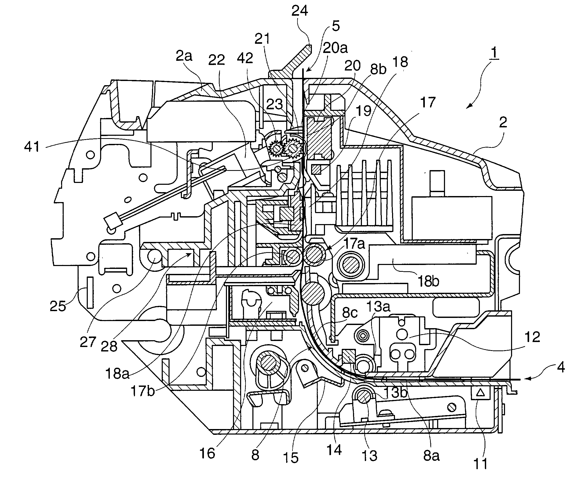
[0016] A further object of this invention is to provide a print media processing apparatus configured to prevent penetration of external light onto the scanning surface, without interfering with print media transportation.
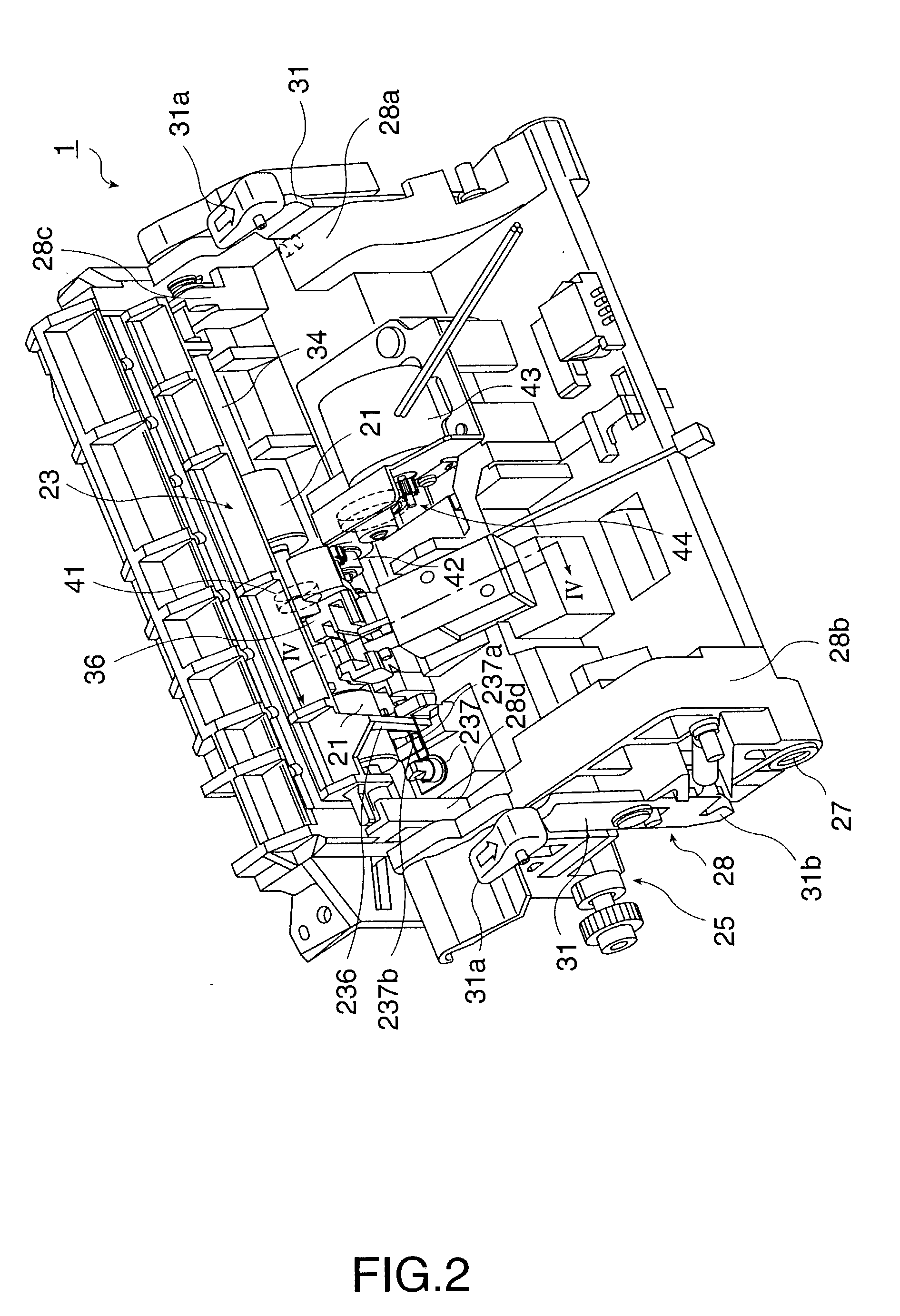
[0140] Note that if the scanner focal position A is offset greatly from the scanner contact position B of the scanner feed rollers 21, the check 3 can move away from the scanning surface 20a at the scanner focal position A. However, by using an offset of only 0.8 mm as in the present embodiment the check 3 separates from the scanning surface 20a by 0.2 mm or less, and there is no concern about a drop in scanned image quality.

Problems solved by technology

However, if the roller continues to press the check against the scanning surface when scanning is not in progress, the roller interferes with smooth check transportation.
If this is done, however, the closed scanner feed roller will interfere with operations when a releasable cover, provided in the printer case for printer maintenance, is opened to, for example, remove a paper jam or replace the ink ribbon.
This method is undesirable, however, because it requires a separate dedicated sensor which increases the number of parts in the apparatus and also its cost.
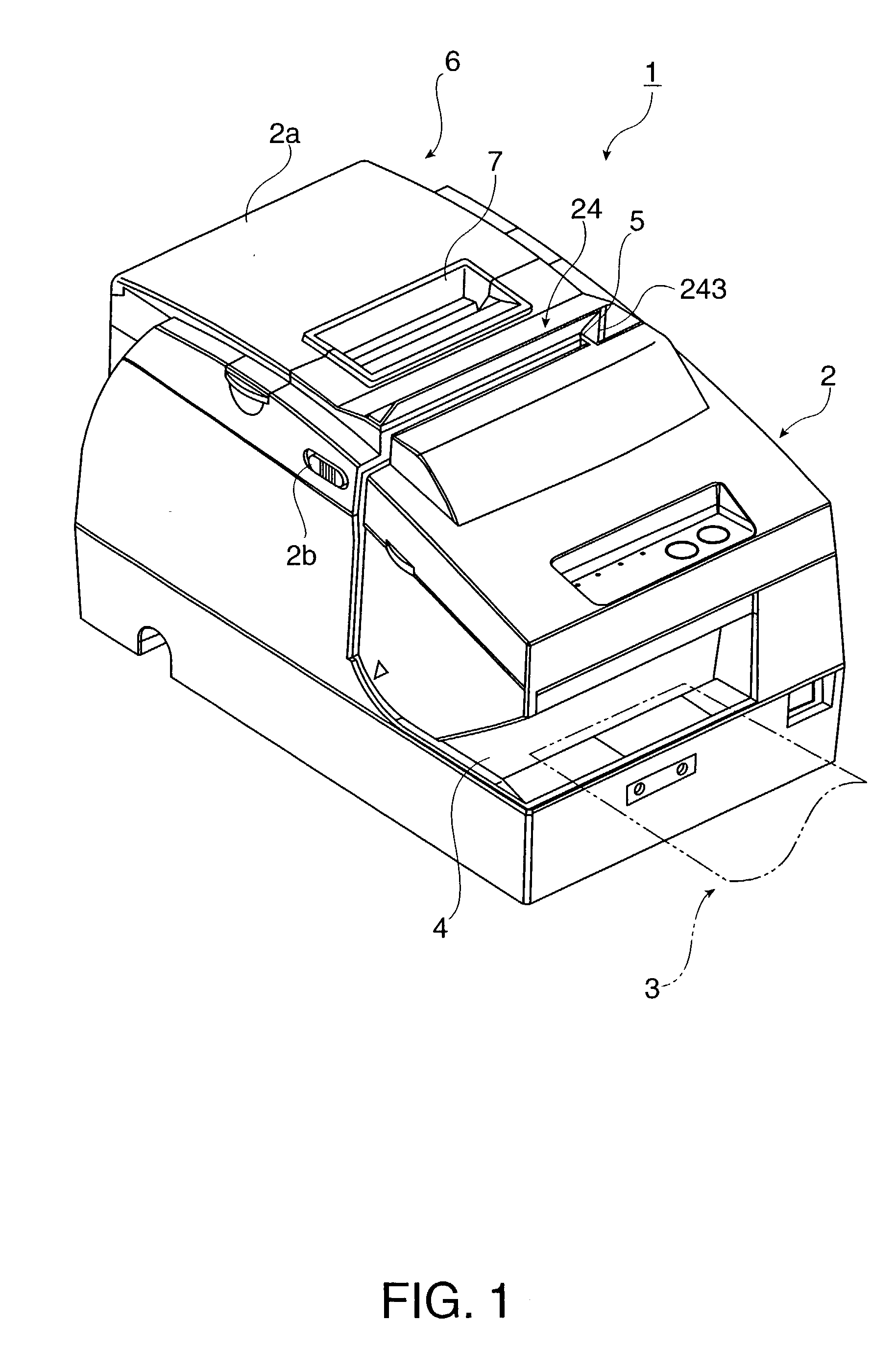
A further problem with this type of multiple function check processing apparatus is that, if the image scanner is located near the check exit opening, external light such as sunlight or internal light can impinge on the scanning surface through the exit opening.
The problem here is that external light incident to the scanning surface causes a drop in the scanning quality of the image scanner.
While this arrangement is convenient for inserting and removing checks, it also makes it easy for sunlight and light from other external sources to enter the inside of the apparatus through the exit opening, contact the scanning surface and thereby degrade the scanning quality.
These problems are not limited to such check processing apparatuses but can also occur in print media processing apparatuses having an image scanner for handling print media other than checks and in more general multifunction printers equipped with a scanner.

Method used


Image

  • Print media processing apparatus and control method for the same
  • Print media processing apparatus and control method for the same
  • Print media processing apparatus and control method for the same

Examples


example 2

Operating Process

[0172] FIG. 18 is a flow chart of another operating mode of the check processing apparatus 1 according to this embodiment of the invention. FIG. 19 shows the position of the check 3 at various times in this operating process. FIG. 20 shows the positions of various components when the check is ejected.

[0173] This operating mode progresses from the second standby state 62 to the MICR process state 64 (steps S1801 to S1807 in FIG. 18), to the MICR post-processing state 65 (steps S1808 to S1811), the printing process state 66 (steps S1812 to S1817), and then returns to the first standby state 61. A check processing command instructing reading the check with the MICR head and printing the check using the print head is received in the second standby state 62 in this example. Each of these states is the same as the operating modes described with reference to FIG. 12 to FIG. 17, and only the process operations that differ are described below.

[0174] More specifically, the op...


PUM


Abstract

A print media processing apparatus having scanner feed rollers for holding and transporting print media against an image scanner appropriately controls the scanner feed roller position. The scanner feed rollers are opposite the image scanner, which is disposed along a vertical segment of a transportation path along which a check or form is transported. A roller retraction mechanism moves the scanner feed rollers between a closed position in which the rollers press against the scanning surface, and an open position in which the rollers are retracted therefrom. The scanner feed rollers retract to the open position a specific time after scanning ends. By delaying retraction of the rollers in this manner, the present invention solves the problem of a check or other print media, after having been processed and transported to the exit side of the rollers, from slipping down between the rollers and the image scanner into the vertical transportation path because the rollers opened as soon as scanning ends.

Description

CONTINUING APPLICATION DATA[0001] This application is a continuation-in-part of application Ser. No. 10 / 172,076, filed Jun. 14, 2002.[0002] 1. Field of the Invention[0003] The present invention relates to a print media processing apparatus having an image scanner for scanning a check or other print medium, and further relates to a control method for such a print media processing apparatus and a program of instructions for implementing the control method.[0004] 2. Description of the Related Art[0005] Print media processing devices capable of performing multiple functions by combining an image scanner or other type of processing device with a printer have been proposed. One such device is a check processing apparatus having a print head, image scanner, and magnetic head. This check processing apparatus runs a printing process for printing essential information on a check, a scanning process to then capture an image of the printed check, and a data transmission process for sending the ...

Claims


Application Information

Patent Timeline
Patent Type & Authority Applications(United States)
IPC IPC(8): H04N1/00H04N1/12
CPCH04N1/00588H04N1/00591H04N1/00602H04N1/00681H04N1/00705H04N1/00734H04N1/00745H04N1/0075H04N1/00755H04N1/00782H04N1/121H04N1/1215
Inventor ENDO, KATSUYUKIMURATA, SADAOFURIHATA, HIDEKI
Owner SEIKO EPSON CORP
Learn More